mc club
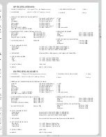
SPECIFICATIONS
ESPECIFICACIONES
9
10. T.H.D (1KHz 0dB OUTPUT)
Master output
Less than 0.05% (LOAD=47K OHMS, 20-20KHz BPF)
Booth output
Less than 0.05% (LOAD=47K OHMS, 20-20KHz BPF)
Phones
Less than 0.3% (LOAD=33 OHMS, 20-20KHz BPF)
11. CROSSTALK
More than 65dB at 1KHz between L and R channels (20-20KHz BPF)
12. CHANNEL EQUALIZER
Bass
+12 ± 3dB / Less than -20dB at 70Hz
Mid
+12 ± 3dB / Less than -20dB at 1KHz
Treble
+13 ± 3dB / Less than -13dB at 13KHz
13. GAIN CONTROL
30dB ± 2dB
14. BOOST
6dB -2/ +3dB at 100Hz
1. POWER CONSUMPTION
12W typical, 27W w /full headphone output.
2. DIMENSIONS
480(W) x 132(H) x 197 tabletop / 184 rack
3. HEADPHONE IMPEDANCE
32 Ohms
4. WEIGHT
4,4 Kgs.
6. MAXIMUM OUTPUT (LOAD=47K Ohms, T.H.D.=5%)
Master output
More than 20dB (10V)
Booth output
More than 20dB (10V)
Rec output
More than 10dB (3.1V)
Phones (LOAD=33 OHMS)
More than 5dB (1.7V)
7. CHANNEL BALANCE
Within 3dB
8. FREQUENCY RESPONSE
Line/CD
20Hz - 20KHz +2dB/-3dB
Phono
20Hz - 20KHz +2dB/-3dB
Microphone
20Hz - 20KHz +2dB/-3dB
9. OUTPUT NOISE (IEC-A,WEIGHTED)
Line/CD
Less than -70dB
Phono
Less than -66dB
Microphone
Less than -60dB
5. INPUT/OUTPUT IMPEDANCE & SENSITIVITY
Line/CD
47K OHM / -14dB (200mV)
+2/-3dB
Phono
47K OHM / -50dB (3mV)
+/-3dB
Microphone
3K OHM / -54dB (2mV)
+/-3dB
Master output
1K OHM / 0dB (1V)
+/-3dB
Booth output
1K OHM / 0dB (1V)
+/-3dB
Rec output
1K OHM / -10dB (316mV)
+/-3dB
Phones (LOAD=32 OHMS)
33 OHM / -3dB (0.7V)
+/-3dB (Stereo/split)
Note: 0dB=1Vrms, LOAD 47K OHMS
10. T.H.D (1KHz 0dB OUTPUT)
Master output
0.05% (LOAD=47K OHMS, 20-20KHz BPF)
Booth output
0.05% (LOAD=47K OHMS, 20-20KHz BPF)
0.3% (LOAD=33 OHMS, 20-20KHz BPF)
11. CROSSTALK
65dB at 1KHz between L and R channels (20-20KHz BPF)
12. ECUALIZADOR DE CANAL
Bass
+12 ± 3dB /
-20dB at 70Hz
Mid
+12 ± 3dB /
-20dB at 1KHz
Treble
+13 ± 3dB /
-13dB at 13KHz
13. GAIN CONTROL
30dB ± 2dB
14. BOOST
6dB -2/ +3dB at 100Hz
Menos de
Menos de
Auriculares
Menos de
Más de
(bajos)
Menos de
(medios)
Menos de
(altos)
Menos de
1. CONSUMO
12W typical, 27W w /auricular al max. output.
2. DIMENSIONES
3. IMPEDANCIA DE AURICULARES
32 Ohms
4. PESO
4.4 Kgs.
480(W) x 132(H) x 197 tabletop / 184 rack
6. CARGA MÁXIMA (LOAD=47K Ohms, T.H.D.=5%)
Master output
Mas de 20dB (10V)
Booth output
Mas de 20dB (10V)
Rec output
Mas de 10dB (3.1V)
Auriculares (LOAD=33 OHMS)
Mas de 5dB (1.7V)
7. BALANCE DE CANAL
Dentro de 3dB
8. RESPUESTA EN FRECUENCIA
Línea/CD
20Hz - 20KHz +2dB/-3dB
Phono
20Hz - 20KHz +2dB/-3dB
Micrófono
20Hz - 20KHz +2dB/-3dB
9. RUIDO DE SALIDA (IEC-A,WEIGHTED)
Línea/CD
Menos de -70dB
Phono
Menos de -66dB
Micrófono
Menos de -60dB
5. IMPEDANCIA Y SENSIBILIDAD DE ENTRADAS Y SALIDAS
Línea/CD
47K OHM / -14dB (200mV)
+2/-3dB
Phono
47K OHM / -50dB (3mV)
+/-3dB
Micrófono
3K OHM / -54dB (2mV)
+/-3dB
Master output
1K OHM / 0dB (1V)
+/-3dB
Booth output
1K OHM / 0dB (1V)
+/-3dB
Rec output
1K OHM / -10dB (316mV)
+/-3dB
Auriculares
(LOAD=32 OHMS)
33 OHM / -3dB (0.7V)
+/-3dB (Stereo/split)
Nota: 0dB=1Vrms, LOAD 47K OHMS
mc club
eng
lis
h
Nivel mínimo audible
Pico (Transient)
Señal electroacústica
Tiempo
Nivel o amplitud
0
1
2
3
4
5
6
7
8
1
2
3
4
Ratio Nivel máximo vs. Nivel mínimo audible
Rango Dinámico
Rango Dinámico
Before unwrapping and starting the mixer there are a few thinks you
should know…
Setting input levels: Gain pot adjusts the input sensibility or so to speak
the level of the input signal inside the mixer. It is paramount to set the
right input level on every channel.
Why is so important setting the correct input level?
First, we have to understand the concept of Dynamic Range of an audio
signal. The Dynamic Range of an audio signal is defined as the ratio
between the maximum level before distortion and the minimum audible
level. It is measured in decibels and gives us an idea of the amplitude of
the signal.
We want the audio signal to
f l u c t u a t e a w a y f r o m t h e
maximum level (distortion
begins) and away from the
minimum level (or background
level), where some noise is
present due the nature of the ICs
used in the electronic circuit (all
ICs induce noise into the audio
signal).
At the draw, we depict this
“ s a f e ” l e v e l w i t h i n t w o
discontinue lines.
We have to set the level of input
signal so that the signal peaks do
not reach saturation levels and
the lower amplitude parts of the
signal are not too near the
background noise level.
We have to acknowledge that a professional audio system is a serial
bounded group of professional audio devices and that saturation or other
signal deterioration present in one device will appear someway or
another at the serial bounded following devices.
If we deliver saturated signal from the mixer to the power amplifier we
will not be able to get rid of this saturation whatsoever. The power
amplifier will amplify all what is given and if noise is given (saturation at
mixer), it will be amplified. Naturally, that is bad.
Using the power amplifier: Saturation and input levels.
In order to make the most of your power amplifier you must watch two
things:
1- Set the volume controls in a way that the saturation LED lights up only
occasionally (peaks).
2- Feed the power amplifier with an audio signal of the appropriate level.
What is the appropriate level? Professional Power Amplifiers are set for
an input level of 4 dBu. Do not panic, it is easy to get to it. 4 dBu is just a
fixed measure of the audio signal that professional audio community
uses as reference level, it can be expressed also in Volts 4dBu equals 1.23
Volt RMS. So to speak, the Power Amplifier will work at its best if feed
with a signal of a level near the 4 dBu or 1.23 Volt RMS. How do we set
this level? Easy, using the mixer appropriately. Incidentally, the nominal
level for a professional audio mixer is also 4dBu. Therefore, if we set the
master output level of the mixer carefully monitoring the output level
meters (normally LED bars), we will ensure that the level of the audio
signal fed to the Power Amplifier is near 4dBu because the nominal level
of the mixer is 4dBu and we set correctly the output level or the mixer.
Antes de comenzar a utilizar su mezclador es muy importante que lea
esta mínima introducción escrita con el propósito de ayudarle a obtener
el máximo partido de su equipo.
Ajustando el nivel de las señales de entrada: El potenciómetro
etiquetado GAIN ajusta la sensibilidad de la entrada de cada canal. Esto
se realiza para ajustar el nivel de las señales de entrada al nivel óptimo de
trabajo del mezclador.
¿Por qué es importante ajustar correctamente el nivel de entrada? Primero
deberemos entender el significado e implicaciones del Rango Dinámico de
la señal. El rango dinámico es el ratio o cociente entre la señal más alta (sin
llegar a distorsión) y la señal audible más baja. Se expresa en decibelios y
nos da una idea de la amplitud de la señal. Una medida equivalente es el
ratio S/N (Signal/Noise o Señal/Ruido).
El nivel de la señal de audio
deberá oscilar entre un nivel
lo más elevado posible
respecto del ruido de fondo y
suficientemente menor que
el nivel de saturación. En el
dibujo se ha delimitado el
área o nivel de trabajo óptimo
m e d i a n t e
d o s
l í n e a s
discontinuas.
El nivel de trabajo óptimo es
aquél que mantiene el nivel
de la señal suficientemente
alejado del ruido de fondo y
permite que los picos de la
señal no excedan el límite de
saturación.
Recuerde que si enviamos a la etapa de potencia una señal saturada del
mezclador, aunque atenuemos los controles de ganancia de entrada de la
etapa la señal seguirá estando saturada. Y el resultado de la
amplificación no será satisfactorio pues estamos amplificando una señal
ya saturada.
Operación de la etapa de potencia: Saturación y niveles de entrada
Para aprovechar al máximo la etapa deberemos ajustar los controles de
nivel de entrada de modo que los LED de saturación “CLIP” sólo se
iluminen ocasionalmente. Las etapas Akiyama AMP tienen un nivel de
entrada nominal de 4 dBu (es un nivel de señal de 1,23 V RMS que
corresponde al estándar de nivel de línea para uso profesional). Es decir,
nuestras etapas trabajarán en óptimas condiciones cuando la señal de
salida de su mezclador hacia la etapa es de 4 dBu. La mayoría de
mezcladores profesionales tienen un nivel nominal de 4 dBu, así pues,
para que la señal entrante en la etapa sea la óptima simplemente
asegúrese de no saturar la señal de salida del mezclador (utilice los LEDs
de nivel del mezclador). Lo adecuado es que los LED rojos (saturación)
sólo se enciendan ocasionalmente.
¿Por qué debemos evitar la saturación? La señal saturada no sólo suena
mal sino que puede destruir nuestras cajas acústicas. No vamos a
extendernos en este tema, simplemente utilice los indicadores LED de la
mesa de mezclas y etapa de potencia para evitar la saturación.
SATURACION
SEÑAL
RANGO DINAMICO
HEADROOM
RA
TIO SEÑAL/RUIDO
!
RUIDO
15 minutos, ¡Léame!
INTRODUCTION / INTRODUCCION
15 min, Read me!
Minimum audible level
Pic (Transient)
Electroacoustic Signal
Time
Level or amplitude
0
1
2
3
4
5
6
7
8
1
2
3
4
Ratio: Max. Level vs. Minimum audible level
Dynamic Range
Dynamic range
en
gl
is
h
SATURA ION
T
S
IGNAL
DYNAMIC RANGE
HEADROOM
RA
TIO S
IGNAL/NOISE
!
NOISE


