4
WARNING!
Operating the equipment incorrectly can cause serious injury and
damage. Do not use the functions described until you have thoroughly read
and understood the following documents:
-
these operating instructions
-
all the operating instructions for the system components, especially the
safety rules
NOTE!
As a result of firmware updates, you may find that there are functions
available on your device that are not described in these operating instructions
or vice versa. Certain illustrations may also differ slightly from the actual control
elements on your device. However, these control elements function in exactly
the same way.
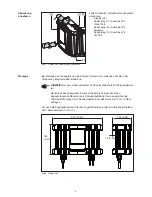
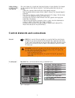
No. Function - Standard version
(1) Charge level indicator
25%
(2) Charge level indicator
50%
(3) Charge level indicator
75%
(4) Charge level indicator
100%
(5) Ready indicator
(6) Stop/start and setup button
-
for interrupting and restarting charging
(7) Error indicator
Fig .3 Control panel
Important!
The control panel (LED version) is explained below.
(1)
(2)
(3)
(4)
(6)
(5)
(7)
The new chargers do not just boast functional features. In terms of safety, the chargers
are also equipped to the highest standards. The following safety features come as
standard:
-
Voltage-free and spark-free terminals protect against explosions
-
Reverse polarity protection prevents the battery or charger from being damaged or
destroyed
-
Short-circuit protection provides effective protection for the charger. The fuse does
not need to be replaced in the event of a short circuit.
-
A charging time monitor provides effective protection against overcharging and
destruction of the battery
-
Thanks to the high degree of protection, there is a lower rate of contamination in
adverse conditions. This adds to the charger’s reliability.
-
Overtemperature protection through derating (charging current reduced if the
temperature rises above the permitted level)
Safety strategy -
standard protec-
tive features
Control elements and connections
General
Control panel

