0
0
-100
0
0
0
0
0
0
0
1
1
12
0
0
0
0
0
1
0
0
0
0
A2
A12
-999*
-999*
0
0
-100
I2
I12
-20
-20
4
4
I3
1
1
1
1
1
23
59
31
12
99
1
2
3
4
6
255
3
1
3
3
999*
999*
A1
A11
120
120
I13
900
900
20
20
1
0
0
0
0
0
0
0
0
0
1
1
12
1
1
1
2
0
1
1
0
0
0
99,9
0
-50
0
0
0
0
100
100
0
0
i1
i11
i2
A0
P2
P3
L2
L4
r1
r2
r3
r4
r5
r6
P8
P50
L1
L3
P5
P7
A10
A4
A14
A1
A11
A2
A12
A3
A13
i12
i3
i13
i4
i14
EP
EP
EP
EP
EP
Level 1
Menus and description
Level 2
Level 2
Level 2
Level 2
Level 2
InP
AL
CnF
dLG
rtC
Input configuration
Alarm configuration
General configuration
Logger configuration
Date and time
Level 3
Level 3
Level 3
Level 3
Level 3
Description
Description
Description
Description
Description
Units
Units
Units
Units
Units
Mín.
Mín.
Mín.
Mín.
Mín.
Def.
Def.
Def.
Def.
Def.
Max.
Max.
Max.
Max.
Max.
(min.)
(min.)
Type of input 1:
0
: Disabled
1
: NTC
2
: 4-20 mA
3
: Digital input (NO)
4
: Digital input (NC)
Type of input 2:
0
: Disabled
1
: NTC
2
: 4-20 mA
3
: Digital input (NO)
4
: Digital input (NC)
Value 4 mA input 1
Alarm input 1:
0
: Disabled;
1
: Enabled
Access code function:
0
: Inactive;
1
:Parameter access block
Default parameters:
0
:No;
1
:Yes
Delete record and event log:
0
:No;
1
:Yes
Decimal separator in .csv files:
0
: ,
1
: .
Hour
Minute
Day
Month
Year
Automatic hour change:
0
: No;
1
: Yes
Input to be displayed:
0
: Carrusel Input 1 - Input 2;
1
: Input 1;
2
: Input 2
Mute alarm with SET key:
0
: Disabled
1
: Only sound
2
: Only relay
3
: Sound and relay
Log interval:
0
: 1 minute
1
: 5 minutes
2
: 15 minutes
3
: 30 minutes
4
: 60 minutes
Day of the start of the log:
0
: Monday
1
: Tuesday
2
: Wednesday
3
: Thursday
4
: Friday
5
: Saturday
6
: Sunday
MODBUS address for units with communication
Temperature display mode:
0
: Integers in ºC
1
: One decimal point in ºC
2
: Integers in ºF
3
: One decimal point in ºF
Alarm input 2:
0
: Disabled;
1
: Enabled
Alarm output input 1:
0
: No output
1
: Only acoustic
2
: Only relay
3
: Ac relay
Alarm output input 1:
0
: No output
1
: Only acoustic
2
: Only relay
3
: Ac relay
MAX alarm value input 1
MAX alarm value input 2
MIN alarm value input 1
MIN alarm value input 2
Delay alarm input 1
Delay alarm input 2
Value 4 mA input 2
Value 20 mA input 1
Value 20 mA input 2
Calibration input 1
Calibration input 2
Output to level 1
Output to level 1
Output to level 1
Output to level 1
Output to level 1
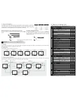
6- Parameter and message table
The
Def.
column indicates the factory default parameters. Unless otherwise indicated, the
temperature values are expressed in ºC (equivalent temperature in ºF).
0
-
-
99
-
-
-
-
-
L5
PU
Pr
EP
EP
Output to level 1
Level 2
tid
Access control and Information
Level 3
Description
Units
Mín. Def. Max.
Password
Programme version
Programme revision
Output to level 1
* the limits may vary depending on the type of input selected
5.2- Alarm log
This function saves an event whenever an alarm is activated or deactivated. To download the events log data, press the
P
key, all the data logged up to date are downloaded onto
the SD card, including the events log, contained in the “ALARMS” folder.
5.3- Initial start-up
The date and time will be requested during the first start-up.
5.4- Programming menu (parameters)
To access the parameter programming menu, press the
N
+
Q
keys at the same time. Refer to the list of available parameters in section 5 of this manual. After 20 seconds without
touching any key, the unit returns to the previous level. If it is in level 3 the changes will not be saved.
Set Hour
N
/
Q
Set
/
Month
N
Q
Set
/
Minutes
N
Q
Set
/
Year
N
Q
Set
/
Day
N
Q
Log start
Press
SET
Press
SET
Press
SET
Press
SET
Press
SET
5.1- Structure of the logged data
-The logged data are stored in the internal memory of the logger organised in log blocks. The period of time stored in each
block, and the maximum capacity of the internal memory, depend on the log interval (L1 parameter), as shown in table.
-The logger has a slot for SD cards, that allows transferring the stored data for display on a computer or to be saved as a
backup. These data are saved in spread sheet format (
.csv),
organised in the following way:
Log interval
Period stored
by block
Internal memory
capacity
1 min.
8 hours
> 50 dias
5 min.
24 hours
> 5 months
15 min.
7 days
> 3 years
30 min.
14 days
> 6 years
60 min.
28 days
> 12 years
*Data of the start of the first log contained in the block.
**File recording date.
Temperature
indication
Level 1
Menus
Level 2
Parameters
Level 3
Values
Change
menu
Change
param.
Change
value
OK
OK
OK
Press
N
+
Q
>10 sec.
Press
N
/
Q
Press
N
/
Q
Press
N
/
Q
Press
SET
Press
SET
Press
SET
Press
SET
Press
SET
Press
N
/
Q
repea-
tedly
Press
N
/
Q
repea-
tedly
20 sec.
20 sec.
20 sec.
OK
OK
OUT OF
PROGRAMMING
IN
PROGRAMMING
·
Year, month
and day**
Year*
Month*
Day, time
and minutes*
Downloads the data of the last closed log or ongoing log (
O
or SET keys)
Each log block is saved in a file, whose name is the day, hour and minutes of the
first log
it
contains.
Downloads ALL the logged data (
P
key)
Two files are generated whose name is the year, month and day of the
download
, in
two different folders ALL and ALARMS. The first contains the file with all the data
logged by the device until then and the second contains the file with the events saved
until then (see section 5.2):
IMPORTANT:
Do not remove the SD card until the indicator turns off.


