AKO Armaturen & Separationstechnik GmbH
Adam-Opel-Str. 5
65468 Trebur-Astheim
DEUTSCHLAND / GERMANY
Telefon / Phone:
+49 6147 9159-0
Fax:
+49 6147 9159-59
E-Mail:
ako@ako-armaturen.de / ako@pinch-valve.com
Internet:
www.ako-armaturen.de / www.pinch-valve.com
1
Technische Änderungen vorbehalten
Subject to technical changes
Ergänzung Betriebsanleitung /
Operating Instruction Supplement
BA-E_ZUEN_2018-08-16
Proportional-Druckregelventil |
Proportional pressure control valve
Original
Translation
Ergänzung zur Betriebsanleitung
Proportional-Druckregelventil, Typ PV.P171
Operating Instructions Supplement
Proportional pressure control valve, Type PV.P171
► Elektrische Installation
(Gerätestecker-Stiftbelegung für Gerätestecker M12 im Gehäuse)
Pin
Bezeichnung
Farbe
1
+ 24V DC Versorgungsspannung
braun
2
Ist-Wert Ausgang
weiß
3
Gemeinsamer Masseanschluss
blau
4
Soll-Wert Eingang (pos.)
schwarz
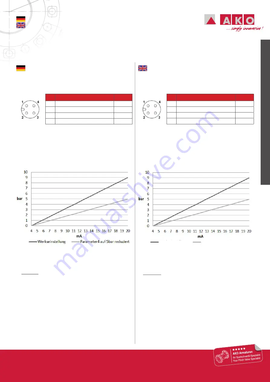
► Einstellung / Zuordnung von Eingangssignal
zum Ausgangsdruck
Werkseinstellung kompletter Bereich / Spanne z.B.:
4 - 20 mA Eingangssignal =
0 - 9 bar Ausgangsdruck
0 - 10 V Eingangssignal =
0 - 9 bar Ausgangsdruck
Es besteht die Möglichkeit, den maximalen Ausgangsdruck bei
gleichbleibendem Eingangssignalbereich zu verringern (z.B.
max. 5 bar).
►
Beispiel:
Betriebs-/Förderdruck:
3,0 bar
Benötigter Steuerdruck (Quetschventil):
ca. 5 bar
Druckluftversorgung:
6,5 bar
(ausreichend, da mindestens 1 bar höher als der max. benötigte Ausgangsdruck /
Steuerdruck (Quetschventil))
Daraus ergibt sich:
4 - 20 mA Eingangssignal =
0 - 5 bar Ausgangsdruck
► Electrical installation
(Device connector pin assignment for M12 device connector
in the body)
Pin
Description
Color
1
+ 24V DC supply voltage
brown
2
Actual value output
white
3
Common ground connection
blue
4
Set point input (pos.)
black
► Setting / assignment of input signal
to output pressure
Factory setting complete range / span e.g.:
4 - 20 mA input signal
=
0 - 9 bar output pressure
0 - 10 V input signal
=
0 - 9 bar output pressure
It is possible to decrease the maximum output pressure at a
constant input signal range (e.g. max. 5 bar).
►
Example:
Operating pressure / feed pressure:
3,0 bar
Required control pressure (pinch valve):
ca. 5 bar
Compressed air supply:
6,5 bar
(sufficient since it is at least 1 bar higher than the max. required output pressure /
control pressure (pinch valve))
This results in:
4 - 20 mA input signal
=
0 - 5 bar output pressure
Factory settings
Parameter4 reduced to 5 bar


