background image


07/2015 

Temperature Difference Controller TDC 3 

Page 15 of 47 


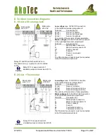
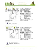
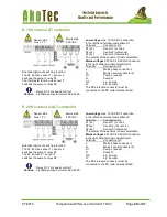
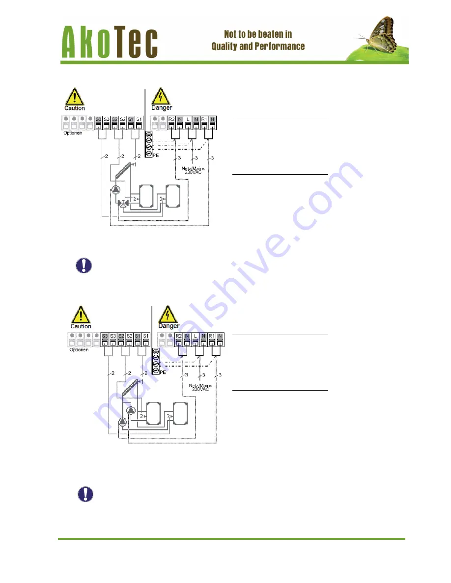
D.9 Solar 2 Storage tank/valve


Actuating direction of valve: 
R2 on/valve on = charge to sensor 3 
(storage tank 2) 


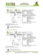
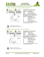
D.10 Solar 2 storage tank/2 pu.


Sensor side 
max. 12 V  

Mains side 
230 VAC  

Low voltage max. 12 VAC/DC connection 
in the left-hand terminal compartment! 
Terminal:  

Connection for: 

S1 (2x)   

Sensor 1 collector 

S2 (2x)  

Sensor 2 storage tank 1 

S3 (2x)   

Sensor 3 storage tank 2 

The polarity of the sensors is freely selectable. 
Mains voltages 230 VAC 50-60 Hz Connection 
in the right-hand terminal compartment! 
Terminal:  

Connection for: 

L  


Mains phase conductor L 

N  


Mains neutral conductor N 

R1  


Pump L (speed) 

N  


Pump N 

R2  


Change-over valve L 

N  


Change-over valve N 

The PE protective conductor must be connected  
to the PE metal terminal block! 

Relay R1: For speed control of 
standard pumps, minimum load 20 VA 


Caution


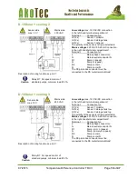
Relay R1: For speed control of 
standard pumps, minimum load 20 VA 


Low voltage max. 12 VAC/DC connection 
in the left-hand terminal compartment! 
Terminal:  

Connection for: 

S1 (2x)   

Sensor 1 collector 

S2 (2x)   

Sensor 2 storage tank 1 

S3 (2x)   

Sensor 3 storage tank 2 

The polarity of the sensors is freely selectable. 
Mains voltages 230 VAC 50-60 Hz Connection 
in the right-hand terminal compartment! 
Terminal:  

Connection for: 

L  


Mains phase conductor L 

N  


Mains neutral conductor N 

R1  


Pump (St.1) L (speed) 

N  


Pump (storage tank 1) N 

R2  


Pump (storage tank 2) L 

N  


Pump (storage tank 2) N 

The PE protective conductor must be connected  
to the PE metal terminal block! 

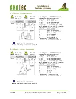
Sensor side 
max. 12 V  

Mains side 
230 VAC  

Caution


Summary of Contents for TDC3

Page 1: ...oduktionsgesellschaft mbH Grundmühlenweg 3 16278 Angermünde Tel 03332 29 66 88 Fax 03212 12 76 490 Email info akotec eu www akotec eu Installation and Commissioning Manual Temperature Difference Controller TDC 3 ...

Page 2: ...27 4 1 Automatic 27 4 2 Manual 27 4 3 Off 27 4 4 Fill system 27 5 Settings 28 5 1 Tmin S1 28 5 2 Tmin S2 28 5 3 Tmin S3 28 5 4 Tmax S2 29 5 5 Tmax S3 29 5 6 T R1 29 5 7 T R2 30 5 8 Tset S3 30 5 9 Hysteresis 30 5 10 Priority sensor 31 5 11 T priority 31 5 12 Loading time 31 5 13 Increase 31 5 14 Thermostat periods 31 5 15 Party Function 32 5 16 Energy saving mode 32 5 17 TecoS3 32 6 Protective func...

Page 3: ... and operation of the unit The valid accident prevention regulations VDE regulations the regulations of the local power utility the applicable DIN EN standards and the installation and operating instruction of the additional system components must also be observed The controller does not under any circumstances replace any safety devices to be provided by the customer Installation electrical conne...

Page 4: ... Warranty and liability The controller has been manufactured and tested with regard to high quality and safety requirements The unit is subject to the statutory guarantee period of two years from the date of sale The warranty and liability shall not include however any injury to persons or material damage that is attributable to one or more of the following causes Failure to observe these installa...

Page 5: ...ge no moisture condensation permitted Other specifications and dimensions Housing design 2 part ABS plastic Installation methods Wall installation optionally panel installation Overall dimensions 163 mm x 110 mm x 52 mm Aperture installation Dimensions 157 mm x 106 mm x 31 mm Display Fully graphical display 128 x 64 dots Light diode Multi color Operation 4 entry keys Temperature sensors may not be...

Page 6: ...xtensive setting menus with explanations Menu block can be activated to prevent unintentional setting changes Resetting to previously selected values or factory settings A wide range of additional functions are available B 2 Scope of supply Temperature Difference Controller TDC 3 3 screws 3 5 x 35 mm and 3 plugs 6 mm for wall installation 6 strain relief clips with 12 screws replacement fuse 2A sl...

Page 7: ... respective hydraulic systems and do not claim to be complete The controller does not replace safety devices under any circumstances Depending on the specific application additional system components and safety components may be mandatory such as check valves non return valves safety temperature limiters scalding protectors etc and must therefore be provided Caution ...

Page 8: ...part of the housing up to the selected position and mark the 3mounting holes Make sure that the wall surface is as even as possible so that the housing does not become distorted when it is screwed on 5 Using a drill and size 6 bit drill 3 holes at the points marked on the wall and push in the plugs 6 Insert the upper screw and screw it in slightly 7 Fit the upper part of the housing and insert the...

Page 9: ... right hand side The customer must provide an all pole disconnecting device e g a heating emergency switch The cables being connected to the unit must not be stripped by more than 55 mm and the cable jacket must reach into the housing just to the other side of the strain relief Relay R1 is only suitable for standard pumps 20 120 VA which are speed controlled via the controller The internal wiring ...

Page 10: ...Installing the temperature sensors The controller operates with Pt1000 temperature sensors which are accurate to the degree thus ensuring optimal control of system functions If desired the sensor cables can be extended to a maximum of 30 m using a cable with a cross section of at least 0 75 mm Make sure that there is no contact resistance Position the sensor precisely in the area to be measured On...

Page 11: ...nductor L N Mains neutral conductor N R1 Pump L speed N Pump N R2 Pump L no speed N Pump N The PE protective conductor must be connected to the PE metal terminal block Low voltage max 12 VAC DC connection in the left hand terminal compartment Terminal Connection for S1 2x Sensor 1 collector S2 2x Sensor 2 storage tank low S3 2x Sensor 3 storage tank top The polarity of the sensors is freely select...

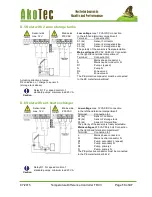
Page 12: ...terminal compartment Terminal Connection for L Mains phase conductor L N Mains neutral conductor N R1 Pump L speed N Pump N R2 Phase valve L N Bypass valve N The PE protective conductor must be connected to the PE metal terminal block Sensor side max 12 V Mains side 230 VAC Low voltage max 12 VAC DC con nection in the left hand terminal compartment Terminal Connection for S1 2x Sensor 1 collector ...

Page 13: ... for L Mains phase conductor L N Mains neutral conductor N R1 Pump L speed N Pump N R2 Zone valve L N Zone valve N The PE protective conductor must be connected to the PE metal terminal block Sensor side max 12 V Mains side 230 VAC Relay R1 For speed control of standard pumps minimum load 20 VA Low voltage max 12 VAC DC connection in the left hand terminal compartment Terminal Connection for S1 2x...

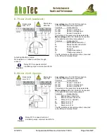
Page 14: ...onductor N R1 Pump L speed N Pump N R2 Change over valve L N Change over valve N The PE protective conductor must be connected to the PE metal terminal block Sensor side max 12 V Mains side 230 VAC Sensor side max 12 V Mains side 230 VAC Relay R1 For speed control of standard pumps minimum load 20 VA Low voltage max 12 VAC DC connection in the left hand terminal compartment Terminal Connection for...

Page 15: ...hange over valve L N Change over valve N The PE protective conductor must be connected to the PE metal terminal block Relay R1 For speed control of standard pumps minimum load 20 VA Caution Relay R1 For speed control of standard pumps minimum load 20 VA Low voltage max 12 VAC DC connection in the left hand terminal compartment Terminal Connection for S1 2x Sensor 1 collector S2 2x Sensor 2 storage...

Page 16: ... L N Mains neutral conductor N R1 Pump L speed N Pump N R2 Pump storage tank 2 L N Pump storage tank 2 N The PE protective conductor must be connected to the PE metal terminal block Sensor side max 12 V Mains side 230 VAC Relay R1 For speed control of standard pumps minimum load 20 VA Low voltage max 12 VAC DC connection in the left hand terminal compartment Terminal Connection for S1 2x Sensor 1 ...

Page 17: ...ment Terminal Connection for L Mains phase conductor L N Mains neutral conductor N R1 Pump L speed N Pump N R2 Pump sec valve L N Pump sec valve N The PE protective conductor must be connected to the PE metal terminal block Sensor side max 12 V Mains side 230 VAC Relay R1 For speed control of standard pumps minimum load 20 VA Low voltage max 12 VAC DC connection in the left hand terminal compartme...

Page 18: ... R2 Pump cooler L N Pump cooler N The PE protective conductor must be connected to the PE metal terminal block Relay R1 For speed control of standard pumps minimum load 20 VA Caution Sensor side max 12 V Mains side 230 VAC Relay R1 For speed control of standard pumps minimum load 20 VA Low voltage max 12 VAC DC connection in the left hand terminal compartment Terminal Connection for S1 2x Sensor 1...

Page 19: ...ns neutral conductor N R1 Pump L speed N Pump N speed R2 Pump solid fuel L N Pump solid fuel N The PE protective conductor must be connected to the PE metal terminal block Sensor side max 12 V Mains side 230 VAC Relay R1 For speed control of standard pumps minimum load 20 VA Caution Low voltage max 12 VAC DC connection in the left hand terminal compartment Terminal Connection for S1 2x Sensor 1 co...

Page 20: ...y of the sensors is freely selectable Mains voltages 230 VAC 50 60 Hz Connection in the right hand terminal compartment Terminal Connection for L Mains phase conductor L N Mains neutral conductor N R1 Pump L speed N Pump N R2 e g pump L N e g pump N The PE protective conductor must be connected to the PE metal terminal block Sensor side max 12 V Mains side 230 VAC Relay R1 For speed control of sta...

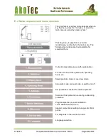
Page 21: ...depending on the situation The esc key 3 is used to cancel an entry or to exit a menu If applicable there will be a request for confirmation as to whether the changes which have been made should be saved The function of each of the other three keys 4 is shown in the display line directly above the keys the right hand key is generally has a confirmation and selection function Examples of key functi...

Page 22: ...issioning help or not The commissioning help can also be terminated or called up again at any time in the special functions menu The commissioning help guides you through the necessary basic settings in the correct order and provides brief descriptions of each parameter in the display Pressing the esc key takes you back to the previous value so you can look at the selected setting again or adjust ...

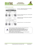
Page 23: ...g menu items are then available for selection there Current temperature values with explanations Function control of the system with operating hours etc Select graphics mode or overview mode Automatic mode manual mode or switch unit off Set parameters needed for normal operation Solar and frost protection recooling antiseizing protection Program selection sensor calibration clock additional sensor...

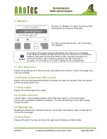
Page 24: ...r esc exits the Info mode Caution If Error appears on the display instead of the measurement value then there may be a defective or incorrect temperature sensor If the cables are too long or the sensors are not placed optimally the result may be small deviations in the measurement values In this case the display values can be compensated for by making entries on the controller Follow the instructi...

Page 25: ...be used to page through the data 2 5 Message log Resetting and deleting the individual analyses The function All statistics clears all analyses but not the error messages 2 6 Reset clear Display of the last 10 events occurring in the system with indication of date and time The menu 2 Statistics is used for function control and long term monitoring of the system The menu is closed by pressing esc o...

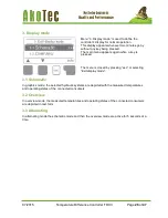
Page 26: ...peratures and operating states of the connected consumers are depicted in text form 3 3 Alternating In alternating mode the schematic mode and then the overview mode are active for 5 seconds at a time Menu 3 Display mode is used to define the controller s display for normal operation This display appears whenever two minutes go by without any key being pressed The main menu appears again when a ke...

Page 27: ...matic mode switched off or placed in a manual operating mode The menu is closed by pressing esc or selecting Exit operating modes Danger When operating mode Manual is activated the current temperatures and the selected parameters are no longer considered There is a danger of scalding or serious damage to the system The operating mode Manual may only be used by specialists for brief function tests ...

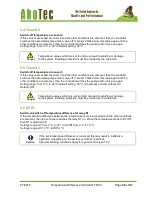
Page 28: ...nge from 0 C to 99 C default setting 40 C 5 3 Tmin S3 Enable start temperature at sensor 3 If this value is exceeded at sensor 3 and the other conditions are also met then the controller switches the associated pump and or valve on If the temperature at sensor 3 drops below this value by 5 C then the pump and or the valve are switched off again Setting range from 0 C to 99 C default setting 20 C T...

Page 29: ...gain Setting range from 0 C to 99 C Default setting 60 C in hydraulic variants without S3 Default Off 5 6 T R1 Switch on switch off temperature difference for relay R1 If this temperature difference between the reference sensors is exceeded and the other conditions are also met then the controller switches the relay R1 on When the temperature drops to T Off then R1 is switched off Settings range T...

Page 30: ... is switched on Setting range from 0 C to 99 C default setting 60 C 5 9 Hysteresis Hysteresis for thermostat function at sensor 3 By setting the hysteresis value the heating of the storage tank can be adjusted If the temperature of the Tsetpoint at sensor 3 is exceeded by the set hysteresis additional heating at relais 2 is deactivated If the Energy saving mode is active see 5 16 the system heats ...

Page 31: ...age tank If so the priority storage tank is charged If not the increase is measured see 5 13 to check if charging of the priority storage tank will be possible shortly Setting range from 5 to 90 minutes default setting 10 minutes 5 13 Increase Extension of the charging pause due to temperature increase in the collector For precise setting of the charging priorities for systems with multiple storag...

Page 32: ...ermostat function In energy saving mode the additional heating via R2 is switched on at TecoS3 and heats up to Teco hysteresis When energy saving mode is active but no solar heat is available TsetS3 is used like in normal mode Settings range On Off Default Off 5 17 TecoS3 Minimum temperature S3 in Energy saving mode If the temperature at sensor 3 falls below this value and the thermostat function ...

Page 33: ...able lists the settings corresponding to the specific programs hydraulic variants The reference sensors 1 3 corresponding to the functions are labelled S1 S3 The switch outputs relays corresponding to the functions for pumps and valves are labelled with R1 or R2 The settings setting ranges and default settings are explained under 5 ...

Page 34: ... Frost stage 1 If the collector temperature drops further to the set value Frost stage 2 the controller switches the pump on continuously If the collector temperature then exceeds the value Frost stage 2 by 2 C then the pump switches off again Frost protection setting range on off default setting off Frost stage 1 setting range from 25 C to 10 C or off default setting 7 C Frost stage 2 setting ran...

Page 35: ...nsfer heat from the collector to the storage tank If CP Ton is exceeded at the collector sensor the pump is switched on until the temperature reaches CP Toff or the temperature CP Tmax storage is exceeded in the storage or pool Collector protection settings range on off Default off CP Ton settings range 60 C to 150 C Default 110 C CP Toff settings range 50 C to Ton minus 5 C Default 100 C CP Tmax ...

Page 36: ...ge tank at S3 exceeds TsetS3 cooling at R2 is switched on till TsetS3 hysteresis is reached 6 5 Col Alarm If this temperature is exceeded at the collector sensor when the solar pump is on a warning or error message is triggered A warning message is shown in the display Collector alarm settings range on off Default off Col alarm setting range 60 C to 300 C Default 150 C 6 6 Recooling In hydraulic s...

Page 37: ...s installed Whenever heating up has been carried out with the anti Legionella function switched on an information message with the date appears on the display Danger During the anti Legionella function the storage tank is heated up over the set value Tmax S2 which can lead to scalding and damage to the system Caution This anti Legionella function does not provide complete protection against Legion...

Page 38: ... S3 per setting range 100 to 100 translates to 50 C 50 C Default setting 0 Menu 7 Special functions is used to set basic items and expanded functions The menu is closed by pressing esc or selecting Exit special functions Caution Other than the time all settings may only be made by a specialist Caution Normally the program selection is made only once during initial commissioning by the specialist I...

Page 39: ...can only be selected and used if additional options or expansions have been built into the controller The associated supplementary installation mounting and operation instructions are then included with the specific expansion 7 7 Heat quantity A simple heat metering function for basic system control can be activated in this menu Additional settings regarding the glycol the percentage of gylcol and...

Page 40: ...0 K actual T 8 K 20 correction value Settings range 50 to 50 default settings 0 7 8 Start aid function With some solar systems especially with vacuum tube collectors it may occur that the measurement value acquisition at the collector sensor occurs too slowly or too inaccurately because the sensor is often not at the hottest location When the start help is activated the following sequence is carri...

Page 41: ...r the control time elapses If the temperature difference T between the reference sensors is below the set value then the speed is decreased by one stage after the control time elapses If the controller has adjusted the speed of the pump down to the smallest stage and the T between the reference sensors is T off the pump is switched off Variant V3 After the purging time the controller switches to t...

Page 42: ... the pump at relay R1 is specified here During the setting the pump runs at the specified speed and the flow rate can be determined Setting range from 70 to 100 default setting 100 7 9 5 Min speed The minimum speed of the pump at relay R1 is specified here During the setting the pump runs at the specified speed and the flow rate can be determined Setting range from 30 to max speed 5 default settin...

Page 43: ... lock on To enable the menus again select Menu lock off Setting range on off default setting off 10 Language Menu 8 Menu lock can be used to secure the controller against unintentional changing of the set values The menu is closed by pressing esc or selecting Exit menu lock Menu 10 Language can be used to select the language for the menu guidance This is queried automatically during initial commis...

Page 44: ...ler TDC 3 Page 44 of 47 9 Service values The menu 9 Service values can be used for remote diagnosis by a specialist or the manufacturer in the event of an error etc Caution Enter the values at the time when the error occurs e g in the table ...

Page 45: ...4 00 Exception see 6 6 Restart Means that the controller was restarted for example due to a power failure Check the date time Time date This message appears automatically after a mains failure because the time date have to be checked and reset if necessary If the controller detects a malfunction the red light flashes and the warning symbol also appears in the display If the error is no longer pres...

Page 46: ...of power Danger Only use the supplied spare fuse or a fuse of the same design with the following specifi cations T2A 250 V Z 2 1 If the mains voltage is switched on and the controller still does not function or display anything then the internal device fuse may be defective In that case open the device as described under C remove the old fuse and check it Exchange the defective fuse for a new one ...

Page 47: ...peration can be switched off using a simple function To do this simply press and hold the esc key down for several seconds on the diagram overview screen A message appears on the display as soon as the pool is switched off or when the pool is switched on again In program 1 Solar with storage tank the mechanical relay R2 switches together with the speed controlled output R1 Relay output R2 can be u...

Reviews: