6600 COUNTS DIGITAL MULTIMETER
USER'S MANUAL
6
2. DESCRIPTION
2.1 Instrument Familiarization
COM
A
V
Hz
mA
uA
A
mA
uA
C
¡ £
Hz
V
OFF
F
¡ £
1
2
3
4
5
6
7
8
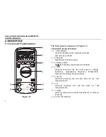
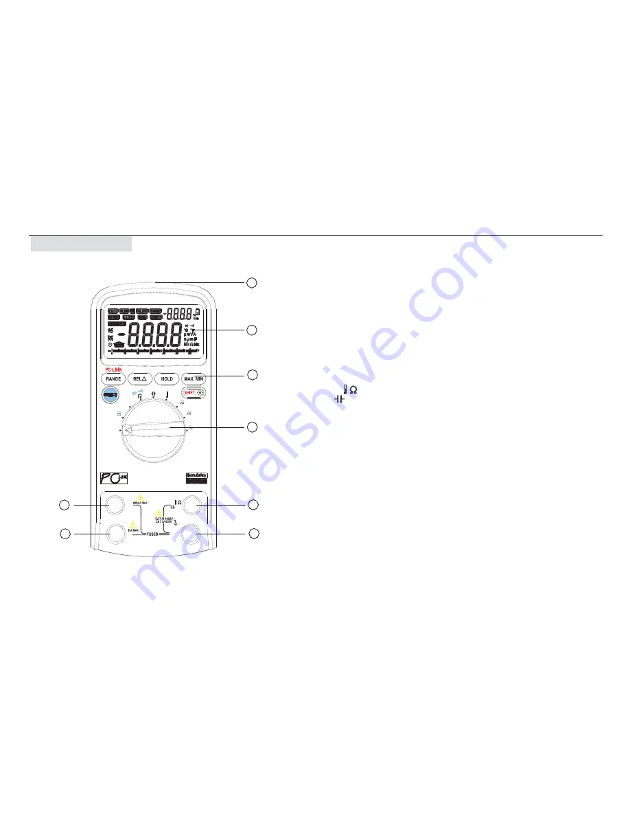
Figure 2-1
The front panel is shown as in Figure 2-1,
explanation being as follows:
ƻ
,1 LCD display
Used for displaying the measuring results
and various symbols.
ƻ
,2 Keypad
Measurement function keys.
ƻ
,3 Rotary switch
Used for selecting measurement functions.
ƻ
,4
V
Hz
Terminal receiving the red test lead for voltage,
resistance, capacitance, frequency, Temperature,
diode and continuity measurements.
ƻ
,5 uA/mA
Terminal receiving the red test lead for
P
A, mA
measurements.
ƻ
,6 A
Terminal receiving the red test lead for 10A
measurements.
ƻ
,7
COM
Terminal receiving the black test lead as a common
reference.
ƻ
,8
PC-Link interface


