background image

6600 COUNTS DIGITAL MULTIMETER   

USER'S MANUAL


29 

5.3 Battery replacement 


To avoid false readings, which could lead to possible electric shock or personal injury, 

replace the battery as soon as the battery indicator ( ) appears.   
Before replacing the battery, disconnect test leads and/or any connectors from any 
circuit under test, turn the meter off and remove test leads from the input terminals.


1. Set rotary switch to the OFF position. 
2. Disconnect test leads and/or any connectors from the terminals. 
3. Use a screwdriver to unlock the two screws on the battery cover.   
4. Take out the battery cover from the meter. 
5. Remove the used battery. 
6. Replace with one new 9V battery (6F22). 
7. Rejoin the battery cover and tighten the screws. 

 
6. ACCESSORIES 

Delivered with the multimeter: 

f

 User's manual 

One piece 

f

 Test leads 

One piece 

f

 "K" type Thermocouple 

One piece 

f

 Multi-function socket 

One piece 

f

 USB line 

One piece 

f

 PC-Link software CD 

One piece 


If there are some changes in accessories, please refer to the real product as standard. 

Summary of Contents for ??-1142

Page 1: ...6600 COUNTS DIGITAL MULTIMETER 1142 User Manual www tmatlantic com...

Page 2: ...rization 6 2 2 LCD Display 7 2 3 Key pad 9 3 FUNCTION DESCRIPTION 11 3 1 General Functions 11 3 1 1 DATA HOLD mode 11 3 1 2 Manual ranging and Autorange mode 11 3 1 3 True RMS measurement 12 3 1 4 Rel...

Page 3: ...mperature measurement 21 3 2 9 PC Link 21 4 TECHNICAL SPECIFICATIONS 22 4 1 General specifications 22 4 2 Measurement specifications 23 4 2 1 AC Voltage 23 4 2 2 DC Voltage 24 4 2 3 Frequency 24 4 2 4...

Page 4: ...TITLE PAGE 5 1 General maintenance 28 5 2 Fuse replacement 28 5 3 Battery replacement 29 6 ACCESSORIES 29...

Page 5: ......

Page 6: ...symbols used on the Meter and in this manual are explained in chapter 1 2 1 1 Precautions safety measures 1 1 1 Preliminary As the possibilities of high transient overvoltages occurred in today s powe...

Page 7: ...fixed installations such as switchgear and polyphase motors Bus and feeder in industrial plants Feeders and short branch circuits distribution panel devices Lighting systems in larger buildings Appli...

Page 8: ...ecification tables When the multimeter is linked to measurement circuits do not touch unused terminals Caution when working with voltages above 60Vdc or 30Vac rms Such voltages pose a shock hazard Whe...

Page 9: ...o not operate the Meter with the case or part of the case removed 1 2 Symbols Symbols used in this manual and on the instrument Caution refer to the instruction manual Incorrect use may result in dama...

Page 10: ...rgize and de energize circuits and equipment in accordance with established practices When the instrument is opened up remember that some internal capacitors can retain a dangerous potential even afte...

Page 11: ...g results and various symbols 2 Keypad Measurement function keys 3 Rotary switch Used for selecting measurement functions 4 V Hz Terminal receiving the red test lead for voltage resistance capacitance...

Page 12: ...6600 COUNTS DIGITAL MULTIMETER USER S MANUAL 7 2 2 LCD Display 1 2 3 4 18 5 6 8 10 9 7 19 11 12 13 14 15 16 17 Figure 2 2...

Page 13: ...lects the range with the best resolution 7 MANU The meter is in the Manual Range mode in which the user selects the range 8 MAX MIN Display maximum minimum data 9 H The meter is in Data Hold mode When...

Page 14: ...ent value with a graphic mode 19 The main display for the meter s measurement value showing all the measurement values 2 3 Keypad 2 3 1 SELECT 1 At position Switches between Resistance measurement Dio...

Page 15: ...to enter the Data Hold mode Used to maintain the measurement data unchanging by pressing the key again it will exit the Data Hold mode 2 Pressing this key and last for 2 seconds the meter will delay f...

Page 16: ...e but the full scale range remains the same Data Hold function can be cancelled by changing the measurement mode pressing RANGE key or push HOLD key again To enter and exit the Data Hold mode 1 Press...

Page 17: ...Relative measurement mode The Meter will display relative measurement in all functions except frequency To enter and exit the relative measurement mode 1 With the Meter in the desired function touch t...

Page 18: ...mode and blanks the display if the Meter is on but not used for 30 minutes Press any key or rotate the rotary switch to wake the meter up 2 To disable the auto power off function hold down REL key wh...

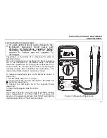
Page 19: ...voltage is constant To measure ac or dc voltage set up and connect the Meter as shown in Figure 3 1 Set the rotary switch to the position ofV 1 Press SELECT key to select between AC and DC voltage mod...

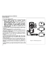
Page 20: ...the rotary switch to the Hz range 2 Insert the black and red test leads into the COM and Hz input terminals 3 Connect the test leads tip in parallel with the circuit to be measured And don t touch an...

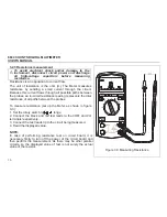
Page 21: ...e reading represents the total resistance of all paths between the probes To measure resistance set up the Meter as shown in figure 3 3 1 Set the rotary switch to range 2 Connect the black and red tes...

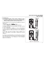
Page 22: ...rminals respectively 4 For forward bias readings on any semiconductor component place the red test lead tip on the component s anode and place the black test lead tip on the component s cathode 5 The...

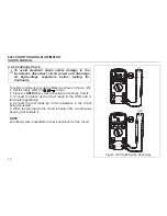
Page 23: ...otary switch to range 2 Press the SELECT key twice to activate Continuity Check 3 Connect the black and red test leads to the COM and terminals respectively 4 Connect the test leads tip to the resista...

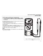
Page 24: ...he capacitor with a known current for a known period of time measuring the resulting voltage then calculating the capacitance The measurement takes about 1 second per range To measure capacitance set...

Page 25: ...asuring AC current the sub display will show the frequency of AC signal 4 Connect the black test lead to the COM terminal and the red test leads to the mA terminal for a maximum of 600mA For a maximum...

Page 26: ...or you can insert it by using Multi Function Socket Takings care to observe the correct polarity 3 Touch the object with the thermocouple probe for measurement 4 Read the stable reading from LCD 3 2...

Page 27: ...SPECIFICATIONS 4 1 General specifications Environment conditions 1000V CAT and 600V CAT Pollution degree 2 Altitude 2000m Operating temperature 0 40 32 122 80 RH 10 non condensing Storage temperature...

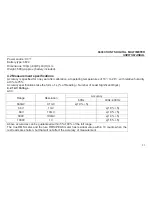
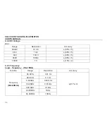
Page 28: ...humidity at 0 to 75 Accuracy specifications take the form of of Reading Number of Least Significant Digits 4 2 1 AC Voltage ACV Accuracy Range Resolution 60Hz 40Hz 400Hz 660mV 0 1mV 1 0 5 6 6V 1mV 1...

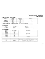
Page 29: ...660mV 0 1mV 0 5 5 6 6V 1mV 0 8 5 66V 10mV 0 8 5 660V 100mV 0 8 5 1000V 1V 1 0 2 4 2 3 Frequency Logic frequency 1Hz 1MHz Function Range Resolution Accuracy 66 00Hz 0 01 Hz 660 0Hz 0 1 Hz 6 600kHz 0 0...

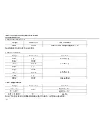
Page 30: ...Above accuracies can be guaranteed within 10 100 of the full range 4 2 4 Duty cycle Range Resolution Accuracy 1 99 0 01 2 10 4 2 5 Resistance Range Resolution Accuracy 660 0 0 1 6 600k 1 66 00k 10 660...

Page 31: ...cription Continuity beeper 30 4 2 8 Capacitance Range Resolution Accuracy 6 6nF 1pF 5 0 5 66nF 10pF 660nF 100pF 6 6PF 1nF 3 0 3 66PF 10nF 660PF 100nF 6 6mF 1PF 5 0 3 66mF 10PF Unspecified 4 2 9 Temper...

Page 32: ...guaranteed within 5 100 of the full range The true RMS meter and the true RMS PEAK meter has residual value within 10 counts when the test leads are shorten but that will not affect the accuracy of me...

Page 33: ...remove all test leads Shake out any dirt that may be in the terminals Soak a new swab with a cleaning and oiling agent such as WD 40 Work the swab around in each terminal The oiling agent insulates th...

Page 34: ...to the OFF position 2 Disconnect test leads and or any connectors from the terminals 3 Use a screwdriver to unlock the two screws on the battery cover 4 Take out the battery cover from the meter 5 Rem...

Reviews: