background image


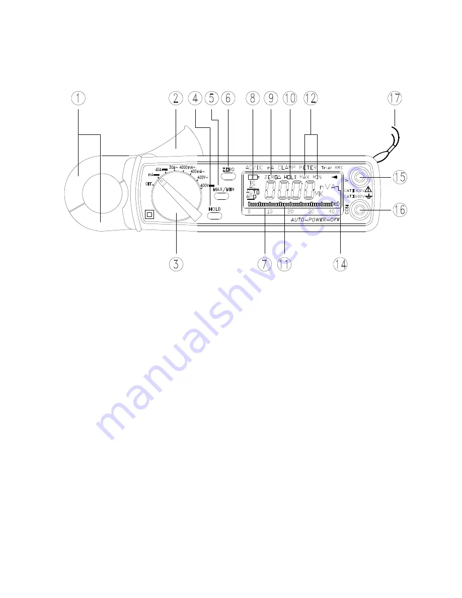
2. Panel Description 


1. Transformer Jaw 
This is used to pick up current signal.    To measure DC/AC current, conductor must 
be enclosed by the jaw. 
2. Transformer Trigger 
This is used to open the jaw. 
3. Function Selector and On/Off Switch 
This is used to select the function user desired, such as DCA, ACA, DCV, ACV. 
4. Data Hold Button 
Once this button is pushed, reading shall be held on the LCD. Press again to release 
it. 
5. Max/Min Hold Button 
This button is used to enable the maximum or minimum value to be displayed and 
updated during measurement.    Press once, minimum value shall be displayed and 
updated.    Press  again,  maximum  value  shall  be  displayed  and  updated.  Zero 
function will be disabled if MAX/MIN is enabled.   
6. Zero/Relative Button 
Once this button is pressed, the current reading shall be set to zero and be used as 
a zero reference value for all other subsequent measurement.    The function is also 
used to remove offset value caused by the residual magetism remained in the core 

www.tmatlantic.com

Summary of Contents for ATK-2001

Page 1: ...U s e r m a n u a l C l a m p m e t e r A K 2 0 0 1 www tmatlantic com...

Page 2: ...ment for connection to circuits in which measures are taken to limit the transient overvoltages to an appropriate low level Overvoltage Category II CAT II Energy consuming equipment to be supplied fro...

Page 3: ...4 Specifications 7 5 Battery Replacement 9 6 Maintenance Cleaning 9 1 Features 1 Accurate DC AC digital clamp meter for current measurement 2 1mA DC 0 1mA AC high resolution 3 One touch zero for DCA a...

Page 4: ...to release it 5 Max Min Hold Button This button is used to enable the maximum or minimum value to be displayed and updated during measurement Press once minimum value shall be displayed and updated Pr...

Page 5: ...tual reading The reading shown is a offseted value Press the zero button again to disable this function 10 Data Hold Symbol Once the hold button is pressed this symbol appears on LCD 11 Bargraph Bargr...

Page 6: ...o in the same direction as in measurement to avoid interference by external magnetic field c Press the trigger to open the jaw and fully enclose the conductor to be measured No air gap is allowed betw...

Page 7: ...leads into the input jack c Connect the test prods of the test leads in PARALLEL to the circuit to be measured d Read the measured value from the LCD display 3 2 2 AC Voltage a Set the rotary switch a...

Page 8: ...the button once the maximum value shall be displayed and updated The LCD display toggles between the MAX and MIN values To exit MAX MIN function press and hold the MAX MIN button for more than 2 seco...

Page 9: ...esolution 50 60 Hz 40 100Hz 400mA 0 1mA 1 5 5dgts 2 0 5dgts AC 40A 50 60 Hz 40 1KHz 4000mA 1mA 2 5 5dgts 3 0 5dgts AC 40A 30A 10mA 2 0 5dgts 2 5 5dgts AC 100A DC Voltage Input Impedance 10M Range Reso...

Page 10: ...ampling Time 3 times sec display 30 times sec bargraph Operating Temperature 10 C to 50 C Operating Humidity less than 85 relative Altitude up to 2000M Storage Temperature 20 C to 60 C Storage Humidit...

Page 11: ...ery compartment 5 4 Remove the old batteries 5 5 Insert two new 1 5V SUM 3 batteries 5 6 Replace the battery compartment and secure the screw 6 Maintenance Cleaning Servicing not covered in this manua...

Reviews: