background image


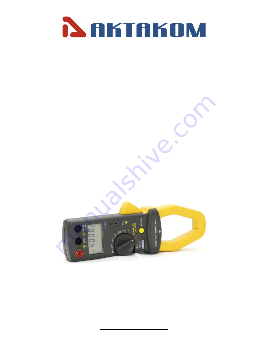
ATK-2209 


Clamp Meter 


User’s Manual 


www.tmatlantic.com

Summary of Contents for ATK-2209

Page 1: ...ATK 2209 Clamp Meter User s Manual www tmatlantic com...

Page 2: ...4 2 AC Current Measurement 10 4 3 1 AC Power KW HP KVA KVAR PF Power Factor and Phase Angle Measurement 10 4 4 3 3W AC Power KW HP KVA KVAR PF Power Factor and Phase Angle Measurement 11 4 5 3 4W AC P...

Page 3: ...ified in this manual otherwise the protection provided by the meter may be impaired Read the operating instructions before use and follow all safety information Caution when working with voltages abov...

Page 4: ...urrent draw in motors and compressors Use MAX MIN Recording in the temperature mode to assess the efficiency Test run start capacitors To identify low voltage control signals Measure flame safeguard d...

Page 5: ...mV to 600 0V Auto Manual 999 9mV 9 999V 99 99V 600 0V AC DC Trms A 0 20 A to 999 9 A Auto Manual 99 99 A 999 9 A Frequency 40 0Hz to 999 9Hz Capacitance 1nF to 7000 F Auto Manual 10 000 F 100 00 F 100...

Page 6: ...ature 0 to 50 32 to 122 and humidity R H 80 non condensing Temperature coefficient 0 1 specified accuracy 18 or 28 64 or 82 Storage temperature 10 to 60 14 to 140 and humidity R H 70 non condensing Di...

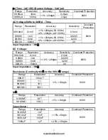
Page 7: ...20V 600 0V 100mV 2V Input impedance 3M DC Voltage Range Resolution Accuracy Sensitivity Overload Protection 999 9mV 0 1mV 1 0 20dgts 2 0mV 600V 9 999V 1mV 0 020V 99 99V 10mV 0 20V 600 0V 100mV 2V Inp...

Page 8: ...r 60 Range Resolution Accuracy Overload Protection 80 00HP 100A 0 01HP 5 rdg 20dgts 50 60Hz 600VAC 1000AAC 800 0HP 100A 0 1HP 1 3 Reactive Power KVAR PF 0 5 or 60 Range Resolution Accuracy Overload Pr...

Page 9: ...m 7 III PARTS CONTROLS 3 1 Description of Parts Control 6 5 10 8 9 MX MN Temp Type K A COM V R lag WL123 m KW X KVAR X F MN MX H 3 4W 3 3W n PF h mm s hp Hz CAT III CAT III 600V 600V 3 4 7 1 2 KVAR C...

Page 10: ...rded Minimum value and time displayed Press MX MN key Shows MX MN on LCD The current value and time displayed Step can be cycled Keep pressing MX MN key for 2 seconds to release Note The default time...

Page 11: ...t lead for Capacitance Resistance Diode Continuity and Micro ampere measurement as a positive terminal IV OPERATING INSTRUCTION 4 1 AC DC Voltage Measurement WARNING Maximum input is 600V Do not attem...

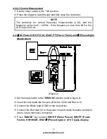
Page 12: ...F Power Factor and Phase Angle Measurement 600V 600V CAT III A V COM CAT III KW KW CAT III COM V A CAT III 600V 600V lag lag Temp Type K MX MN Figure 2 Set the rotary switch to the KW KVA position ref...

Page 13: ...ment First measure WRS L1L2 refer to figure 3 a Set the rotary switch to the V b Keep pressing HOLD key then set the rotary switch to KW KVA the 3 3W and WL12 symbol appear c Insert the test leads int...

Page 14: ...refer to figure 4 a Disconnect the test probe from the phase where jaws is clamp on in previous measurement b Connect the test probe to the third phase eg T or L3 c Camp the third phase where test pro...

Page 15: ...be shown to indicate the watt of 3 3W power refer to figure 5 At this moment the watt of 3 3W power is stored to the memory KW CAT III COM V A CAT III 600V 600V lag 3 3W WL123 Figure 5 If willing to r...

Page 16: ...S or L2 phase is always connected to the COM during measurement of WRS or WL1L2 and WTS or WL3L2 in 3 3W unbalanced power NOTE 1 The sign printed on Panel must face the power source for accurate meas...

Page 17: ...he first phase eg R or L1 f Clamp on to the same phase eg R or L1 g The power clamp meter will automatically select proper range h Wait until the reading is stable about 6 seconds press the HOLD key a...

Page 18: ...T III A V COM CAT III KW lag lag WL 2 3 4W 3 4W WL 2 3 4W WL 2 KW CAT III COM V A CAT III 600V 600V MX MN Figure 7 Third measure WT L3 refer to figure 8 a Disconnect the test probe from the phase wher...

Page 19: ...III A V COM CAT III KW Figure 8 The power clamp will process these three sets of data WL1 WL2 WL3 and show the result on the LCD WL123 symbol will be shown to indicate the watt of 3 4W power refer to...

Page 20: ...t NOTE In the 3 4W power measurement all three WR or WS and WT must be positive If users find one negative power check the connection of test leads and clamping of jaw Make sure all the connections an...

Page 21: ...tary switch to the Temp position Press RANGE key to select desired or temperature units Insert the Type K thermocouple to the Temp jack Use temperature probe to touch the object being measured and rea...

Page 22: ...s before removing back cover As battery power is not sufficient LCD will display Replacement with one new battery type 9 V is required Set Range switch to OFF position Use a screwdriver to unscrew the...

Reviews: