www.tmatlantic.com
18
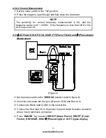
If willing to read the details of that singly data record, please “
HOLD
”
key to select desired WL1, WL2, WL3 or WL123 display then press
“RANGE” key to select
KW+HP (Horse Power), KW+PF (Power Factor),
KW+KVAR, KVA+
θ
(Phase Angle) or A+V 5 types display.
W
3
φ
4W
= W
R(L1)
+ W
S(L2)
W
T(L3)
KVA
KW
KVAR
W
W
W
3 4
2
3 4
2
3 4
φ
φ
φ
=
+
PF
KW
KVA
W
W
W
3 4
3 4
3 4
φ
φ
φ
=
Set the rotary switch to other position exit this mode and clear the
stored data.
NOTE
1. The "+" sign printed on Panel must face the power source for
accurate measurement.
2. If the device under test is switching mode power, the meter KW, PF
and
θ
reading maybe incorrect.
NOTE
In the 3
φ
4W power measurement, all three WR or W
S
and WT must be
positive. If users find one negative power, check the connection of test
leads and clamping of jaw. Make sure all the connections and clamping
are correct to obtain correct power.
4-6 Resistance & Continuity Measurement
WARNING
Before taking any in circuit resistance measurement, remove Power form the
circuit being tested and discharge all capacitors.
Before taking resistance measurements, make sure the circuit is not live and
discharge any capacitors present in the circuit.
Set the rotary switch to the "
Ω
,
" or "M
Ω
" range.
Insert the test leads into the input jack. (Black to COM and Red to
Ω
).
Connect the test leads to the circuit being measured and read the displayed
value.
When the reading is below 40
Ω
,
it will be indicated by a continuous beeping.


