background image

ASM 


USER’S MANUEL 

PAGE: 26 


03.04-B1


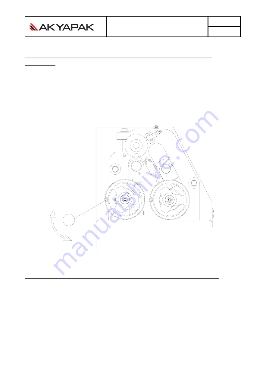
9.10. THE LOW ROLL MATERIAL COMPESSION (UP –DOWN 
MOVING) 


1-


Bring the lower top rolls up,turning the arm 01-number. 


2-


After the sheet metal tightening between the lower and upper top rolls,  

take the bending sheet out,the lower sheet metal must bring down.Of this do the same operation 
opposite. 


01


9.11. TAKEN THE BENDING MATERIAL OUT OF THE MACHINE


After the bending operation of the material ,bring the lower rolls down and; 
 
1- Take out the upper roll eccentric . So the upper top rolls bearing will come off position. 
 
2- Pull the upper top rolls shaft sttraight yourself.Take out the shaft from the housing. 
 
3- Take out the bending material from the opening space. 


Summary of Contents for ASM

Page 1: ...S MANUEL PAGE 1 03 04 B1 ASYMETRICAL 3ROLLER BENDING MACHINE ASM AKYAPAK Mak San ve Tic Ltd Şti Akçalar Sanayi Bölgesi 16225 Akçalar BURSA TÜRKIYE Tel 0090 224 280 75 00 Fax 0090 224 280 75 02 www akyapak com tr ...

Page 2: ... production in our factory is suitable to the standards below Eropean standards and instructions are listing at the table below Machine Name ASYMETRICAL 3 ROLLER BENDING MACHINE Machine type ASM Production year And serial number 2013 EC Instruction EC Terms 98 37 EC EC Low Voltage Terms 73 23 EC EC Eloctro Magnetic Terms 89 336 EC i d F 93 31 EC EC Standards DIN EN 292 1 DIN EN 292 2 DIN EN 60204 ...

Page 3: ...tions of the parts and some reactions of the machine V Rest of the other principal conditions which are not the subject of warranty cases are listed below Please notice that those conditions are not gradual but also covers all similar situations Warranty does not provide extra time with decleration of disgrace or the claim for asking a justice Buyer can not claim any written or oral justice oppose...

Page 4: ...near the machine working area ATTENTION Only the autorized personal may use this machine All the modifications making on the machine without the autorized personal AKYAPAK is not responsible for the accidents When the operator is leaving the working place the machine key will close O Position and the machine voltage will stoped Don t stripp the safety elements on the machine The operator reading t...

Page 5: ...SM110 20 2 0 2050 2 0 3 0 110 150 2 2 2820 1150 850 1350 ASM120 10 4 5 1050 4 5 5 0 120 175 2 2 1820 1150 850 1150 ASM120 12 4 0 1270 4 0 4 5 120 175 2 2 2020 1150 850 1250 ASM120 15 3 5 1550 3 5 4 0 120 175 2 2 2320 1150 850 1300 ASM120 20 2 5 2050 2 5 3 0 120 175 2 2 2820 1150 850 1420 ASM130 10 5 0 1050 5 0 5 5 130 190 2 2 1820 1200 850 1220 ASM130 12 4 5 1270 4 5 5 0 130 190 2 2 2020 1200 850 ...

Page 6: ...ASM USER S MANUEL PAGE 6 03 04 B1 4 Machine measurement ...

Page 7: ...riate at CE Standards 5 2 SPECIAL EQUIPMENTS 9 Induction hardened rolls 9 Back shaft with motor 9 Digital display 6 SAFETY FACTORS 6 1 THE MACHINE DANGER AREAS The bottom and upper shafts asymetrical cylinder machine are rotationable When the machine is working don t put your hands on the cylinders and protect your working dresses from the pressing It is will be very danger When the machine is wor...

Page 8: ...r 9 The dresses and the other things 9 The deformation of the bending material 9 When the material is bending the other worker staying near the machine 9 The bending accesories of the machine According to the right using of the machine and maintenanse all the personal is responsible Don t bend the hard material on the machine outside the aluminium material The lossing on the machine and on himself...

Page 9: ... of the material in mm This values are valid for the material quality St 37 If the material flow limit and the quality is changeable the value should be changeable also 6 4 The machine setting plan When the machine is assembly be careful about the machine place and surroundings factor necessity The place for assembly must be hard and strong Check the weight machine for the safety of the working Th...

Page 10: ...nding operations the operator must be take safety dispositions and control step by step completely all the operations Surround the machine at the bending operation the max parts of the material must be take at the reliable place and the other personel must not enter there The right using of the machine is given below EME RG STO P 6 6 RISKS ARISING FROM THE ACCESSORIES IN THE MACHINE When the acces...

Page 11: ...r personal come near the working place the operator is responsible for him from the wound and damage The machine can work only at the closed area To working the machine at the explosive containing the gas and burning dangerous areas is forbidden The producer is not responsible for the parts and accessories which are not original and using at the time of the repairing the machine When you come near...

Page 12: ...damage at the equipments and parts changing on the machine 7 PROTACTION FACTORS The protection factors for the operator working at the machine are warning equipments attached below in 7 1 Chapter check list This protaction factors are separate attached for USER CONTROL THE PROTACTION FACTORS 9 Before every work in relays control the protaction factors 9 Once at the week periodicaly control the saf...

Page 13: ... 7 2 THE LOSSES AT THE TRANSPORTATION ATTENTION Take out the plastic protaction package when you receive the machine If you fixing from the transportation any damage write at the documentation farwording agency this not and inform the producer for the looses WARNING The USER must read the user manuel use and start the machine in appropriate way The user must not take out the safety elements For ex...

Page 14: ...gency and inform the manufacturer company for the damage The children must not contact with the package material if the plastic and chemistry material are higher The package must pull out with the gloves During the carriage the varios parts of the machine are lubricate with oil The oil may cleaning with diesel or solvent 7 6 THE MACHINE ASSEMBLY PLAN ON THE GROUND The main screw machine must screw...

Page 15: ... lenght must be L 1 5 rigid and Lx1 5 cavity 3 The machine side border must leave a margin cavity 1 meter to moving the bending sheet material 7 8 MAIN PLAN The machine must be connecting on the hard and strong ground for the security of the working machine The cement quality using on the ground basis must be appropriate to the machine weight and the ground The machine must place after 72 hour on ...

Page 16: ...ust be repair only at the side qualifed electrician personel Before repairing the technical characteristics on the table must be controling Fit the energy cable into the hole auxiliary the machine Assembly the energy cable in the clamps L1 L2 L3 N PE inside the electrical panel 8 2 CONNECTING THE CONTROL PANEL TO THE MACHINE Take the control panel near the side machine and put the plug inside the ...

Page 17: ...machine must be assembling To strengthen the rope must be use the angular arms Screw this arms to the surround the machine Place the rope inside the round of the pulley and tight them To adjust the switch the end of the rope must stretch over showing below and the button will pulling up and straight For the security machine is assembly the safety rope To stopping the machine touch slowly the rope ...

Page 18: ...er 1 Present the inside machine electrical panel For each motor are using 2 At the extremely current situation the motor this electrical parts stop the current circuit 3 At the normaly working on the circuit breaker position 1 if the motor take the extremely current the thermic will cutting the circuit machine and the circuit breaker will take the position 0 To take the position 1 again the thermi...

Page 19: ...ASM USER S MANUEL PAGE 19 03 04 B1 9 1 CONTROL PANEL 7 6 6 FOOT PEDAL EMERG STOP 7 FOOT PEDAL 5 EMERGENCY STOP BUTTON 4 VOLTAGE EXPANDING POISON 3 STOP 2 START 1 CIRCUIT BREAKER 1 5 2 4 3 ...

Page 20: ... quality material which are very important as below 1 The quality of the material 2 Yield point 3 Elasticity module 4 If the thicknees of the material at all the places is not the same the material will be without homogeneous 5 The material fibre direction This factors are very important The dimensions can not get again if one of them is changing before bending operation For example with the same ...

Page 21: ...ty bending material The step for this operations 1 The bending material absolutely must place between the top rolls 2 The bending material absolutely must be paralel to the top rolls axis 9 5 BENDING OPERATION The first operation is giving the machine power The other operations are following 1 Turn the power switch to position 1 rear the face electrical panel 2 Check the power lamp is lighting or ...

Page 22: ...ASM USER S MANUEL PAGE 22 03 04 B1 9 6 THE MACHINE METOD FOR THE BENDING OF THE MATERIAL FORM 1 FORM 5 FORM 2 FORM 6 FORM 4 FORM 8 FORM 3 FORM 7 ...

Page 23: ... of the other side RE ŞEKİL 7 To reaching the require diameter rotate the rear shaft top rolls up ŞEKİL 8 Reaching to the requiring diameter one or two time rotate the material and make the calibre The important component for the right measured bending material is the development sheet metal According the bending form the development of the sheet metal must correct accounting and cutting At the be...

Page 24: ...because THE HALF USING FOR THE MACHINE NORMAL CAPACITY This mean the machine 2000 mm x 6 mm the thickness sheet metal and the capacity of the cone bending the half of the capacity can bend 1000 mm x 3 mm If you want make at the below illustration the end of the cone is cutting you must prepare the diameter and lenght the sheet metal development This development is prepare at the following formula ...

Page 25: ... 3 Rotate the rear shaft arm C and take up the rear shaft to the requiring dimension z The rear shaft opposite end hold down according to the cone position Form 1 4 According the requiring dimensions take the rear shaft up put forward the clutch shaft and tighten the headless bolt Form 1 5 As development for the cutting and bending material on the body rest are present the cone bending apparatus f...

Page 26: ...out the lower sheet metal must bring down Of this do the same operation opposite 01 9 11 TAKEN THE BENDING MATERIAL OUT OF THE MACHINE After the bending operation of the material bring the lower rolls down and 1 Take out the upper roll eccentric So the upper top rolls bearing will come off position 2 Pull the upper top rolls shaft sttraight yourself Take out the shaft from the housing 3 Take out t...

Page 27: ...er machine Because the dimension which is geting with the side top rolls is related how many unit are moving completely The digital display show us how many rear top rolls shaft are positioning that is to say how many unit is moving For many bending parts when the first part is finish to bending the display take notes for the rear top rolls shaft position this value for the next bending materials ...

Page 28: ...d materials on the machine if only the rolls are hardened The machine working atmosphere must not effective from the atmosphere conditions and must be witout the dust Especially must to pay attention for the lift screw at the bottom and side rolls shaft This lift screw must control every day by run an eye over lubricate and clean their surface from the strange parts 10 3 CHECKING THE ABRASION PART...

Page 29: ...ASM USER S MANUEL PAGE 29 03 04 B1 11 GREASE In the machine are using two kind of the grease Grease Liquid grease 11 1 GREASE POINTS ...

Page 30: ...OMPARISON TYPE Graese Liquid MOBIL Kup Grease 2 Mobil Gear 629 BP Energrease GP2 Energol GR XP 150 SHELL Livona 2 Omala Oil 150 CASTROL Helvium 2 Alpha SP 150 TEXACO Meropa 150 ELF Reductelf SP 150 TOTAL Carter EP 150 ESSO Spartan EP 0 AGIP Blasia 150 Q8 Goya 150 ...

Page 31: ...ASM USER S MANUEL PAGE 31 03 04 B1 12 SPARE PARTS PLAN ...

Page 32: ...ASM USER S MANUEL PAGE 32 03 04 B1 12 1 SPARE PARTS PLAN 1 UPPER ROLLS SHAFT ...

Page 33: ...ASM USER S MANUEL PAGE 33 03 04 B1 12 2 SPARE PARTS PLAN 2 REAR ROLLS SHAFT ...

Page 34: ...ASM USER S MANUEL PAGE 34 03 04 B1 12 3 SPARE PARTS SCHEME 3 BOTTOM ROLLS SHAFT ...

Page 35: ...LABELS USED ON THE MACHINE ÜRETİCİ FİRMA ETİKETİ MANUFACTURER COMPANY LABEL MAKİNE BİLGİ ETİKETİ MACHINE DETAILS LABEL YAĞ ETİKETİ MACHINE OIL LABEL ASM USER S MANUEL PAGE 35 ...

Page 36: ...UYARI ETİKETİ WARNING LABEL İŞ GÜVENLİĞİ UYARI ETİKETİ WORKING SAFETY WARNING LABEL ASM USER S MANUEL PAGE 36 ...

Page 37: ...ERATOR ONESELF 12 6 11 SAFETY FACTORS AT THE MACHINE ASSEMBLY 12 6 12 IMMEDIATE SITUATION TO DO 12 6 13 WARNING SAFETY FACTORS 12 7 PROTACTION FACTORS 13 7 1 PROTACTION FACTOR CHECKING LIST 13 7 2 THE LOSSES AT THE TRANSPORTATION 14 7 3 THE MACHINE PROTACTION 14 7 4 TRANSPORT AND RAISING THE MACHINE 14 7 5 EXTRACTING THE PACKAGE 15 7 6 THE MACHINE ASSEMBLY PLAN ON THE GROUND 15 7 7 SETTING KNOWLED...

Page 38: ...G MATERIAL OUT OF THE MACHINE 27 28 9 12 ADJUSTMENT OF THE DIGITAL DISPLAY 28 10 MAINTENANCE 29 10 1 PROTACTION OF THE MAINTENANCE 29 10 2 REGULAR CLEANLINESS 29 10 3 CHECKING THE ABRASION PARTS IN THE MACHINE 29 10 4 REPAIRING THE FAILURE 29 11 TO GREASE 30 11 1 TO GREASE THE NEEDED POINTS 30 11 2 THE TABLE FOR THE GREASE COMPARISON 31 12 SPARE PARTS PLAN 32 12 1 SPARE PARTS PLAN 1 33 12 2 SPARE ...

Reviews: