background image


Operation and Configuration 


akYtec GmbH · Vahrenwalder Str. 269 A · 30179 Hannover · Germany Tel.: +49 (0) 511 16 59 672-0 · www.akytec.de  


24


– 

in case of the analog control Output 1 will be set to the level specified in the parame-
ter 

mvEr

 (PID safe state) 

In the Network control mode the output signal will be set to the last saved output level. 

Set 

r-S 

= StoP to deactivate the alarm. Set 

r-S 

= rUn to resume control. The detailed 

descriptions of errors and remedy actions are given in Table D.1. 

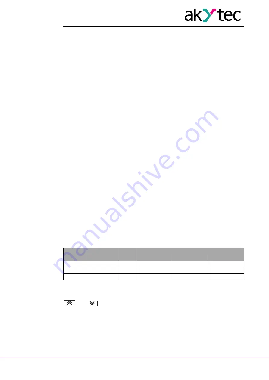
6.15  Stop state 

When control is stopped, the control output will be set to the level specified in the


param-

eter: 

– 

onST

 – Output 1 state when on-off control is OFF 

– 

mdST

 – Output 1 state when PID control is OFF 

If 

mdST

 = o, the output signal will be set to the last saved output level 

If 

mdST

 = mvST, the output signal will be set to the level specified in the parameter


mvST 

(PID stop level).  

6.16  RS485 network settings 

To establish communication via RS485 connect the RS485 lines to terminals D+ and D- 
(see 5.1) and set the following network parameters in the menu group 

Comm 

(see Table 

C.1): 

Prot


– Protocol (akYtec, Modbus RTU, Modbus ASCII) 

bPS


– Baud rate (2.4…115.2 kbit/s) 

A.LEn


– Address bits (7, 8) 

Addr


– Network address. Valid values: 

0…255 for 

Prot

 = 

OWEN

  and 

A.LEn

 = 8 

0…2047 for 

Prot

 = 

OWEN

  and 

A.LEn

 = 11 

0…247 for 

Prot

 = 

MRTU

  or 

MASC 

rSdL


– Response delay (1…45 ms) 

Note:

 The changed network parameter values come into effect only after restarting the 

device (power off and on again or via Network). 

The following invariable network parameters are not available in the system menu (see 
Table 6.5). 

Table 6.5   Invariable network parameters 

Parameter 

Name 

Protocol 

akYtec 

Modbus RTU 

Modbus ASCII 

Stop bits 

Sbit 

Data bits 

LEn 

8 bit 

8 bit 

7 bit 

Parity 

PrtY 

none 

none 

none 

6.17  Factory settings 

To reset the device to the default settings switch it off 

at least for 1 minute,

 hold the 

 and 

 keys together and then switch the device on. When 

[– – – –]

 appears 

on the upper display, release the keys. The settings will be reset to default values. 

6.18  Calibration 

The device should be calibrated to restore the accuracy after a long-term operation or 
repair works with an effect on the measurement system. Calibration has to be carried out 
by the manufacturer. 

Contact the Technical Support of akYtec GmbH for further details. 

Summary of Contents for TRM210

Page 1: ...GmbH Vahrenwalder Str 269 A 30179 Hannover Germany Tel 49 0 511 16 59 672 0 www akytec de TRM210 PID controller User guide TRM210_2018 04_0240_EN All rights reserved Subject to technical changes and misprints ...

Page 2: ...5 2 Inputs 10 5 2 1 Linear signals 10 5 3 Outputs 11 5 3 1 Relay outputs R 11 5 3 2 NPN transistor T 11 5 3 3 TRIAC C 11 5 3 4 Solid state relay S 12 5 3 5 Analog 4 20 mA I 12 5 3 6 Analog 0 10 V U 12 6 Operation and Configuration 13 6 1 Control elements 13 6 2 Principle of operation 14 6 3 Configuration 15 6 4 Temperature sensor 15 6 5 Linear signal 15 6 6 Filter 16 6 7 Correction 17 6 8 Digital ...

Page 3: ...1 6 14 2 Loop Break Alarm 23 6 14 3 Safe state 23 6 15 Stop state 24 6 16 RS485 network settings 24 6 17 Factory settings 24 6 18 Calibration 24 7 Control 25 7 1 General 25 7 2 Stand alone control 25 7 3 Autotuning 25 7 4 Manual Tuning 26 7 5 Manual Control 26 7 6 Control over Network 26 7 7 Error 27 8 Maintenance 28 9 Transportation and storage 29 10 Scope of delivery 30 Appendix A Dimensions 31 ...

Page 4: ...oaded from www akytec de 1 2 Functions The PID controller TRM210 is designed for creating automatic control and regulation systems of various technological processes in different areas of industry agriculture and utilities The controller provides following basic functions measuring of the process value and its transformation according to the sensor type displaying the process values and configurat...

Page 5: ...ions always occur at each of the two ends of the bus the first and the last node The higher the data transmission rate the stronger the reflections are A terminat ing resistor is needed to minimize reflections 150 ohm 0 5 W resistor can be used as a line termination The TRM210 can only be used as a Slave device PLC computer with SCADA software or device can be used as a Master device To establish ...

Page 6: ...ielded twisted pair STP Enclosure H1 H2 H3 Dimension mm 96 x 96 x 70 96 x 48 x 100 105 x 130 x 65 IP Code front IP54 front IP54 IP44 Table 2 2 Linear signals Signal type Measurement range Accuracy 0 1 V 0 100 0 5 50 50 mV 0 100 0 5 mA 0 100 0 20 mA 0 100 4 20 mA 0 100 Table 2 3 Temperature sensors Signal type Measurement range C Temperature coefficient C 1 Accuracy RTD according to IEC 60751 2008 ...

Page 7: ...V AC constant operation 0 5 A f 50 Hz pulse duration 5 ms S Solid state relay 100 mA 4 6 V DC I 4 20 mA 10 36 V max 1 kohm U 0 10 V 15 36 V min 2 kohm 2 1 Environmental conditions The device is designed for natural convection cooling that should be taken into account when choosing the installation site The following environment conditions must be met clean dry and controlled environment low dust l...

Page 8: ... indicates a potentially harmful situation which if not avoided may result in damage of the product itself or of adjacent objects 3 1 Intended use The device has been designed and built solely for the intended use described in this guide and may only be used accordingly The technical specifications contained in this guide must be observed The device may be operated only in properly installed condi...

Page 9: ...ooth so that the IP54 protection for H1 and H2 can be provided The device can be placed at any angle Maximum panel thickness is 15 mm 4 2 Mounting Mounting procedure for panel mount H1 or H2 housing prepare the mounting cutout for H1 Fig A 1 or H2 Fig A 2 and Fig 4 1 housing make sure that the device is provided with the mounting seal fit the device into the cutout insert the 2 fastening clips int...

Page 10: ...wn or flashover Different phases are not allowed 5 1 General The layout of terminal blocks is shown in Fig 5 1 and the terminal assignments in Table 5 1 Ensure that the device is provided with its own power supply line and electric fuse I 0 5 A Connect the power supply to the terminals L N The inputs should be wired in accordance with Fig 5 1 The outputs should be wired in accordance with Fig 5 2 ...

Page 11: ...15 ohm Equal length and cross section 2 or 3 wire TC 20 m 100 ohm Compensation cable Current signal 100 m 100 ohm 2 wire Voltage signal 100 m 5 ohm 2 wire Use wires of equal length and cross section when connecting RTD Use a thermocouple cable when connecting TC Thermocouple sensing junctions of both inputs must be isolated from each other and from the grounded equipment Cold junction compensation...

Page 12: ...e are designed to control low voltage relay up to 60 V DC 400 mA NOTICE As a precaution against inadvertent current reversal on the output a parallel diode Imax 1 A Umax 100 V is usually included in the output circuit Fig 5 3 NPN transistor outputs 5 3 3 TRIAC C The resistor R1 5 20 kohm is used to limit the load current NOTICE To protect thyristors and TRIACs from overload a RC protect circuit sh...

Page 13: ...utput 5 3 5 Analog 4 20 mA I For the current output an external voltage source is required NOTICE The auxiliary voltage must not exceed 36 V The output is designed for maximal load resistance of 1 kohm Fig 5 7 4 20 mA output 5 3 6 Analog 0 10 V U An external power supply is required for analog output 0 10 V NOTICE The auxiliary voltage must not exceed 36 V The output is designed for minimal load r...

Page 14: ...ow following information Table 6 1 Displays Display Mode Displayed information Upper display red Operation Process value Configuration Parameter name Menu MENU Error Error name Lower display green Operation Setpoint Configuration Parameter value Menu Parameter group For display functions during the configuring see section 6 3 Configuration Table 6 2 Indicators LED Indication Description OUT1 light...

Page 15: ...put The digital input has only one function i e Remote start stop see 6 8 In the control mode the analog input is continuously sampled the signal is converted according to the selected sensor type in t parameter see Table B 1 and the measured value is displayed and processed according to the input settings The Control Unit analyses the input value and generates the control signal on the Output 1 T...

Page 16: ...red temperature can be set in the parameter dPt Decimal point displayed The parameter is not available in the menu for sensors with the linear output For the thermocouples with the upper limit above 1000 C is recommended to set dPt 1 for other temperature sensors dPt 0 When the thermocouple is used Cold junction compensation CJC enables precise tem perature measurement The reference junction senso...

Page 17: ...rameter Fb in measuring units within the range 0 9999 The filter is disabled if the bandwidth is set to 0 The difference between the last two measurements Ti and Ti 1 is determined and com pared with the bandwidth If the difference exceeds the bandwidth the last measurement Ti will be replaced with the Ti 1 Fb and the bandwidth will be doubled to smooth the characteristic curve A smaller filter ba...

Page 18: ...Offset Fig 6 7 Slope 6 8 Digital input The control process can be stopped or started with a switch connected to the digital input see Fig 6 2 The parameter Ev 1 Digital Input Function specifies whether the function Remote start stop with a closed or an open contact is active Ev 1 nonE digital input inactive Ev 1 n o control start with an open contact control stop with a closed contact Ev 1 n C con...

Page 19: ...9 Setpoint limits and 6 10 6 Setpoint Ramp The control procedure depends on the output type and can be set in the parameters de scribed below see 6 10 1 6 10 6 6 10 1 Control type CntL Pid PID control CntL onoF on off control Note If Control is started the parameter CntL is not available in the menu The parame ter can be only modified when the control process is stopped in the menu by setting r S ...

Page 20: ...d by the proportional band constant that multi plies the deviation Pv SP I component defined by the integral time constant the time required by the integral component to generate the output equivalent to the proportional com ponent D component defined by the derivative time constant the time re quired by the proportional component P to repeat the output provided by the deriva tive component D For ...

Page 21: ...r vSP per minute The higher the Setpoint Ramp the slower the response time Increase the value or set vSP 0 if the process cannot be controlled properly 6 12 Outputs In the device with the digital output the PID control is applied as a pulse width modulation PWM with Pulse period CP and Pulse duration of Output signal x CP The device with the analog output is used for analog PID control or for retr...

Page 22: ... The parameters An L and An H can be set in measuring units and are only for analog output available The valid range for An L and An H is limited by the measuring range for temperature sensors or by in L in H parameters for linear signals The setting An L An H is not allowed 6 14 Alarm There are two alarm functions Range Alarm and Loop Break Alarm LBA Both alarm functions can control digital outpu...

Page 23: ...alarm 06 As for 02 but with blocking of the first alarm 07 As for 03 but with blocking of the first alarm 08 Value greater than AL d 09 Value less than AL d 10 As for 08 but with blocking of the first alarm 11 As for 09 but with blocking of the first alarm If ALt 0 the alarm comparator will be deactivated and the parameters AL d and AL H unavailable AL d parameter can assume values within the rang...

Page 24: ...0 LBA Time countdown begins Curve I if the LBA Time is exceeded and the temperature keeps going down the alarm is activated Fig 6 12c Curve II if the process value starts growing but the variation does not reach the LBA Range within the LBA Time the alarm is activated as well Fig 6 12c Fig 6 12 LBA Time is measured in seconds and can be determined as follows set the output signal to maximum measur...

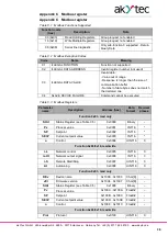
Page 25: ... menu group Comm see Table C 1 Prot Protocol akYtec Modbus RTU Modbus ASCII bPS Baud rate 2 4 115 2 kbit s A LEn Address bits 7 8 Addr Network address Valid values 0 255 for Prot OWEN and A LEn 8 0 2047 for Prot OWEN and A LEn 11 0 247 for Prot MRTU or MASC rSdL Response delay 1 45 ms Note The changed network parameter values come into effect only after restarting the device power off and on again...

Page 26: ...pends on the type of output For digital output indicator is on the output is activated indicator is off the output is deactivated In the devices with analog output the flashing indicator shows the output signal level The indicator is off when the output signal is at its lowest level 4 mA for current 0 V for voltage The indicator starts to flash once per second when the output signal level begins t...

Page 27: ...he controller are only controlled by the oper ator using the functional keys also Remote start stop is not available To use the Manual Control go to the LmAn menu group To display the group in the menu make sure that CntL Pid Stand alone control is activated see 7 2 At StoP Otherwise the group LmAn doesn t appear in the menu Press the key to enter the group Once the first parameter o Ed Manual out...

Page 28: ...trol Note 1 The parameters r L and r oUt are only available via network 2 The parameter r L is initiated with 0 every time the device is switched on or restarted via Modbus using the command init see Table C1 Comm group 7 7 Error The device monitors the integrity of the transmitters connected to the inputs Sensor error is generated when the sensor fails or when the measured value is outside the me...

Page 29: ...ng of the housing and terminal blocks from dust dirt and debris checking the fastening of the device checking the wiring connecting leads fastenings mechanical damage The device should be cleaned with a damp cloth only No abrasives or solvent containing cleaners may be used The safety information in section 3 must be observed when carry ing out maintenance ...

Page 30: ...ovides optimum protection If the device is not taken immediately after delivery into operation it must be carefully stored at a protected location The device should not be stored in an atmosphere with chemically active substances Permitted storage temperature 25 55 C NOTICE Transport damage completeness The device may have been damaged during transportation Check the device for transport damage an...

Page 31: ...Scope of delivery akYtec GmbH Vahrenwalder Str 269 A 30179 Hannover Germany Tel 49 0 511 16 59 672 0 www akytec de 30 10 Scope of delivery TRM210 1 Short guide 1 Mounting kit 1 Gasket 1 ...

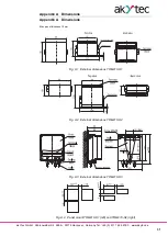
Page 32: ...ver Germany Tel 49 0 511 16 59 672 0 www akytec de 31 Appendix A Dimensions Max panel thickness 15 mm Fig A 1 External dimensions TRM210 H1 Fig A 2 External dimensions TRM210 H2 Fig A 3 External dimensions TRM210 H3 Fig A 4 Panel mount TRM210 H1 left and TRM210 H2 right ...

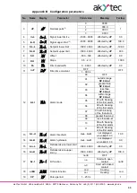
Page 33: ...ted by dP 30 0 3 r S r S Remote Start Stop rUn Start StoP StoP Stop 4 At At Autotuning rUn Start StoP StoP Stop 5 o O Control 0 100 read only Basic settings init 1 in t in t Sensor r385 Pt50 Pt100 r 385 Pt100 r391 50P GOST r 391 100P GOST r 21 46P GOST r426 Cu100 r 426 Cu50 r 23 53M GOST r428 50M GOST r 428 100M GOST E_A1 A E_A2 A 2 GOST E_A3 A 3 GOST E__B B E__J J E__K K E__L L GOST E__N N E__R R...

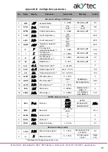
Page 34: ...nt OFF OFF 1 999 s 12 ALt ALT Alarm mode 00 OFF 00 01 outside range SP AL d 02 greater than SP AL d 03 less than SP AL d 04 within range SP AL d 05 01 with blocking of the first alarm 06 02 with blocking of the first alarm 07 03 with blocking of the first alarm 08 greater than AL d 09 less than AL d 10 08 with blocking of the first alarm 11 09 with blocking of the first alarm 13 AL d AL d Alarm th...

Page 35: ...ffected by dP 20 10 db db Deadband 5 0 200 affected by dP 0 11 oL L oL L Output lower limit 5 0 oL H 0 12 oL H oL H Output upper limit 5 oL L 100 100 13 orL OrL Output signal ramp 5 0 2 100 s 100 14 mvEr MVEr PID safe state 5 0 100 0 15 mdSt MdSt PID stop state 5 mvSt mvSt value mvSt o last output value 16 mvSt MVSt PID stop level 5 0 100 0 17 LbA LbA LBA time 5 0 9999 s disabled when LbA 0 0 18 L...

Page 36: ... 511 16 59 672 0 www akytec de 35 2 Displayed for linear signal only 3 Displayed for analog output 2 only 4 Displayed for on off control only CntL onof 5 Displayed for PID control only CntL Pid 6 Valid values 0 255 for Prot OWEN and A LEn 8 0 2047 for Prot OWEN and A LEn 11 0 247 for Prot M RTU or M ASC ...

Page 37: ...not match the declared one 04 SLAVE DEVICE FAILURE Command cannot be executed Table C 3 Modbus Registers Parameter name Description Address hex Data format Decimal places Function 0х03 read only StAt Status Register see Table C 5 0x0000 Binary Pv Process value 0x0001 INT16 SP Setpoint 0x0002 INT16 SEt P Current setpoint value 0x0003 INT16 o Control 0x0004 UINT16 0 Function 0х03 0x10 read write r L...

Page 38: ...6 SH Offset 0x0205 INT16 KU Slope 0x0206 UINT16 3 Fb Filter bandwidth 0x0207 UINT16 inF Filter time constant 0x0208 UINT16 0 SL L Setpoint lower limit 0x0300 INT16 SL H Setpoint upper limit 0x0301 INT16 orEU Control function 0x0302 UINT16 0 CntL Control type 0x0303 UINT16 0 CP Pulse period 0x0304 UINT16 0 rAmP Quickly to Setpoint mode 0x0305 UINT16 0 P P component proportional band 0x0306 UINT16 i...

Page 39: ... n is used where X integer value n power of 10 specified in the column Decimal places for each parame ter INT16 2 byte signed integer When transmitting the parameter the format Х 10 n is used where X integer value n power of 10 specified in the column Decimal places for each parame ter Float32 4 byte floating point Big endian Char 8 String of 8 symbols 1 byte each direct order Hex word 2 byte inte...

Page 40: ...0 Displayed tempera ture differs from the current temperature Control mode Wrong sensor type Select the correct sensor type Incorrect Offset or Slope settings Set the correct values in parame ters SH or KU If no correction is required set SH 0 and KU 1 2 wire connection without correction See 6 7 Correction Electromagnetic interfer ence Use only shielded sensor line ground the shield on one point ...

Reviews: