Installation
akYtec GmbH · Vahrenwalder Str. 269 A · 30179 Hannover · Germany Tel.: +49 (0) 511 16 59 672-0 · www.akytec.de
8
4
Installation
CAUTION
Improper installation
Improper installation can cause serious or minor injuries and device damage.
Installation must be performed only by fully qualified personnel.
The device is designed in a plastic enclosure for panel or wall mounting. For the dimen-
sion drawings see Appendix A.
4.1
Requirements
–
Install the device in a cabinet with clean, dry and controlled environment. For further
details see 2.1.
–
The device is designed for natural convection cooling that should be taken into ac-
count when choosing the installation site.
–
The seal contact surface must be clean and smooth, so that the IP54 protection (for
H1 and H2) can be provided.
–
The device can be placed at any angle.
–
Maximum panel thickness is 15 mm.
4.2
Mounting
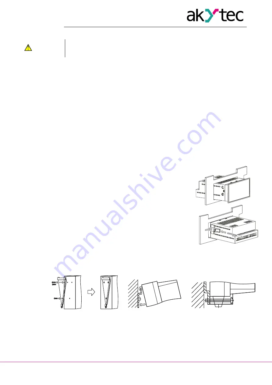
Mounting procedure for panel mount (H1 or H2 housing):
–
prepare the mounting cutout for H1 (Fig. A.1) or H2 (Fig.
A.2 and Fig. 4.1) housing
–
make sure that the device is provided with the mounting
seal
–
fit the device into the cutout
–
insert the 2 fastening clips into the slots on the sides of the
device
–
insert the screws and tighten them to fix the device
Mounting procedure for wall mount (H3):
–
prepare three drilled holes according to Fig. A.3
–
fix the triangle mounting bracket to the wall using three
М4x20 screws (not included) (see Fig. А
.3 and Fig. 4.2a)
–
hook the angle bracket on the back of the device on the
upper edge of the triangle bracket (Fig. 4.2b)
–
fix the device to the triangle bracket with the screw sup-
plied (Fig. 4.2c)
Fig. 4.1 Panel mount
a)
b)
c)
Fig. 4.2 Wall mount


