background image

16

Translation of original user instructions

Assembly

Parts Overview

 (Illustration 1)


1

Cutting blade

2

String Head

3

Protective hood

4

"Bike" bicycle grip

5a/5b Accelerator Lever

6

Motor switch "off" and "on"

7a/7b "Latch" gas lever

8

Carrying strap

9

Air fi lter shroud

10

Gasoline tank

11

Lever "Choke" - "Run"

12

Primer (cold-start diaphragm pump)

Caution!

The device many only be operated after completed 

assembly.

Mount hand grip

D-Grip (BC 410) (Illustration 3)

Lay rubber packing (2) over the support bar. 

1. 

Screw (4) upper grip half (3) and lower grip half (1) to 

2. 

one another.

"Bike" bicycle grip (BC 4125) (Illustration 2A, B)

Lay rubber packing (3) over the support bar.

3. 

With the aid of four hexagon socket screws (1) secure 

4. 

the lower brace (2) and the center piece (4) .

Lay grip rod (5) into the grip holder and secure with 

5. 

the upper brace (6) and the four hexagon socket 

screws (7).

Mount protective hood 

(Illustration 5)

Lay thickness gauge (2) under the protective hood (3). 

1. 

Affi x 4 screws (1) to protective hood.

2. 

The integrated blade in the protective hood automatically 
cuts the cutting string to the optimal length.

Mount String Head

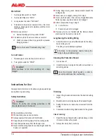
Remove cotter pin 

1. 

(Illustration 4-4) and 

fl ange(Illustration 4-3 ).

Insert allen key 

2. 

(Illustration 6-2) into the bore on the 

drive plate (Illustration 6-1), and screw the string head 

onto the guide pin on the drive shaft. 

(Caution: Left-hand thread!)

Lock drive plate 

3. 

(Illustration 6-1) with the allen key, in 

order to apply the string head.

Mount cutting blade

Disassemble the half, smaller protective layer on the 

1. 

protective hood  (Illustration 5  

Æ

). 

Remove cotter pin 

2. 

(Illustration 4-4) and fl ange 

(Illustration 4-3 ).

Lay the cutting blade in such a way on the drive plate, 

3. 

that the bore on the cutting blade lies exactly on the 

leading circle on the drive plate. 

Attach the fl ange 

4. 

(Illustration 4-3) in such a way that 

the cutting blade points the fl at side toward the cutting 

blade. 

Securely tighten the clamping nut on the guide pin. 

5. 

For this, insert the allen key (Illustration 4-5) into the 

provided bore and secure with the key. 

(Caution: Left-hand thread!)

Secure the nut with the cotter pin.

6. 

Set-up Shoulder Strap

Strap shoulder strap over the left shoulder.

1. 

Hook the locking hooks into the eyelet.

2. 

Test the shoulder strap length with several swinging 

3. 

movements, without leaving the motor on.String 

cutting head or cutting blade must run parallel to the 

ground.

Caution!

Always use the shoulder strap when working.
Only hook up shoulder strap after motor starts in an idle 
state.

Summary of Contents for BC 410

Page 1: ...BC 410 BC 4125 INFORMATION I MANUALS I SERVICE 463 914_e I 08 2009 GB F I SLO DK N PL SK D NL E H HR S FIN CZ QUALITY FOR LIFE User Manual RUS UA 057 BG RO TR...

Page 2: ...ER GROUP K tz Germany This documentation or excerpts therefrom may not be reproduced or disclosed to third parties without the express permission of the AL KO KOBER GROUP Subject to technical alterati...

Page 3: ...di istruzioni 46 H Haszn lat 54 SLO Navodilo za uporabo 62 HR Upute za uporabu 70 DK Brugsanvisning 78 S Bruksanvisning 86 N Bruksanvisning 94 FIN K ytt ohjeet 102 PL Instrukcja obs ugi 110 CZ N vod...

Page 4: ...4 BC 410_4125 1 2A 2B 7 M6x25 6 5 2 4 3 1 M6x40...

Page 5: ...5 463 914_e 10 4 2 5...

Page 6: ...e ser Dokumentation und auf dem Ger t Diese Dokumentation ist permanenter Bestandteil des beschriebenen Produkts und sollte bei Ver u erung dem K ufer mit begeben werden Sicherheitshinweise Ger t nur...

Page 7: ...BC 4125 Motortyp Luftgek hlter 2 Takt Motor Luftgek hlter 2 Takt Motor Hubraum 32 6 cm 32 6 cm Leistung 0 85 kW 0 85 kW Trockengewicht 7 5 kg 7 8 kg Treibstoff Fassungsverm gen 1 l 1 l Schallleistung...

Page 8: ...nsch Bild 4 3 entfernen Sechskantschl ssel 2 Bild 6 2 in die Bohrung der Mit nehmerscheibe Bild 6 1 stecken und den Fadenkopf auf den F hrungsdorn der Antriebswelle schrauben Achtung Linksgewinde Mitn...

Page 9: ...le durchf h ren Mit losem besch digten oder abgenutzten Schneid werk und oder Befestigungsteilen darf das Ger t nicht benutzt werden Motor starten Warnung Motor nie in geschlossenen R umen laufen lass...

Page 10: ...ebel voll gedr ckt halten bis der Mo tor ruhig l uft Motor springt nicht an Startklappe auf Position RUN stellen Starterschnur 5x ziehen Springt der Motor wieder nicht an 5 Minuten warten und anschlie...

Page 11: ...adenkopf leicht nach vorne neigen Trimmen an Steinmauern Fundamenten B umen f hrt zu einem erh hten Fadenverschleiss M hen Fadenkopf im 30 Grad Winkel nach rechts neigen 1 Handgriff in die gew nschte...

Page 12: ...beh r sind aus recycling f higen Materialien hergestellt und entsprechend zu entsorgen Vergasereinstellung Der Vergaser ist ab Werk optimal eingestellt Z ndkerze Bild 9 Z ndkerzenelektrodenabstand 0 6...

Page 13: ...lter Filter ersetzen Motor startet aber l uft nicht mit voller Leistung Falsche Hebelposition am Choke Hebel auf RUN setzen Verschmutzter Luftfilter Filter reinigen oder ersetzen Motor l uft sprunghaf...

Page 14: ...umentation and on the device This documentation is a permanent component of the described product and should be handed over for the disposal of the buyer Safety Guidelines Only use the device when it...

Page 15: ...String diameter 2 4 mm 2 4 mm Cutting blade cutting width 25 cm Grip D grip Bike grip Ignition Electronic Electronic Sparkplug NGK BPMR8A or the equivalent NGK BPMR8A or the equivalent Drivetrain Cent...

Page 16: ...4 and flange Illustration 4 3 Insert allen key 2 Illustration 6 2 into the bore on the drive plate Illustration 6 1 and screw the string head onto the guide pin on the drive shaft Caution Left hand t...

Page 17: ...inspection If there are loose damaged or worn out cutting works and or fastening parts the device must not be used Always operate trimmer with protective shield Always observe country specific rulings...

Page 18: ...Warm Start Set the ignition switch on Start 1 Set the start flipper on RUN 2 Lock gas lever as under Cold start 3 Pull starter cord quickly a maximum of 6x the motor 4 starts up Press gas lever comple...

Page 19: ...and nudge the string head lightly forward Trimming along stone walls foundations and trees leads to increased string waste Mowing Nudge string head at a 30 degree angle to the right 1 Place the handg...

Page 20: ...assured once again Caution Risk of injury from rotating cutting head Only adjust Bowden cables with the engine switched off Only check the function with the strimmer lying down Storage Empty fuel tank...

Page 21: ...or replace Dirty fuel filter Replace filter Motor starts but does not run with full performance Wrong lever position on choke Set lever on RUN Dirty air filter Clean or replace filter Motor runs spasm...

Reviews: