493357_a
15
Assembly
be put into operation as described in the operat-
ing instructions:
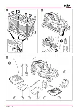
1. Fitting of the steering wheel
2. Fitting of the steering column cover with igni-
tion lock
3. Installation of the operator's seat
4. Assembly of the grass catcher
5. Fitting of the grass catcher
6. Installation and connection of the starter bat-
tery
5.1
Fitting steering wheel (04)
1. Turn the front wheels to the straight-ahead
position.
2. Fit steering wheel (04/1) with the extension
on steering column (04/2, 04/a).
Note:
Make sure the position is correct with
the spoke facing towards the operator.
3. Secure the extension by inserting hexagon
head bolt (04/3) through the extension and
steering column.
Note:
Observe the prescribed tightening
torque of 35 Nm + 5. Use a torque wrench.
4. Secure the hexagon head bolt with a lock nut
(04/4).
5.2
Fitting steering column cover (05- 12)
Once the steering wheel has been installed, the
steering column cover with ignition lock and the
disengagement linkage (depending on the model)
must be installed:
1.
Appliances with infinitely variable hydrostat
drive only:
■
Remove cotter pin (05A/5) and washer
(05A/4) from disengagement linkage (05A/1).
■
Position disengagement linkage (06/1) at
the end of shift linkage (06/2).
■
Push the disengagement linkage through
the free opening at the end of shift link-
age (05B/3) and then fix it again with
washer (05B/4) and cotter pin (05B/5).
2. Disassemble steering column cover(07/1) by
loosening the 6 mounting screws (07/2).
3. Insert rear steering column cover (with igni-
tion lock) (08/1) into the recesses (08/2) on
the ride-on mower.
4. Connect cable (09/1) of the ignition lock to
cable (09/2) of the ride-on mower (09/a).
5.
Appliances with infinitely variable hydrostat
drive only:
Insert disengagement linkage
(10/1) through the lateral opening of cover
(10/2) and fix it using knob (10/3) supplied.
6. Secure front cover:
■
Insert front cover (11/1) into the recesses
on the ride-on mower (11/a).
■
Insert and tighten the 6 mounting screws
(12/1) again.
5.3
Installing operator’s seat (13, 14)
1. Fold seat bracket (13/1) forwards.
2. Position seat (13/2) in front of the seat brack-
et and insert mounting screws (13/3).
3. Fold the seat bracket with seat (14/1) back
again and push it forwards or back to adjust
the position to suit the operator (14/a).
4. Fold the seat bracket forward and tighten
mounting screws (14/2) of the seat.
5.4
Fitting grass catcher (15 – 23)
1. Assemble catcher frame (15/1) and screw to-
gether using nuts and bolts at the indicated
points (15/2).
2. Loosen all nuts and bolts adjust the catcher
frame to the required position (16).
3. Push the frame into grass catcher (17/1) so
that the bracket for the carrier bar is protrud-
ing out of the top of the grass catcher. En-
sure that the solid part of the grass catcher is
at the bottom.
4. Clip the plastic sections onto the frame (18,
19) using a screwdriver (19/1).
5. Place carrier bar (20/1, 20/a) from above on-
to the frame and screw the carrier handle on
tightly using the screws supplied (20/2).
6. Push extension lever (21/1) into grass catch-
er (21/a).
7. Insert a screw (22/1) to prevent the extension
lever from sliding out of the bracket.
8. Hook the assembled grass catcher into the
recesses on the ride-on mower (23).
9. Fold down the grass catcher (23/a) and
check whether safety switch (23/1) is tripped.
5.5
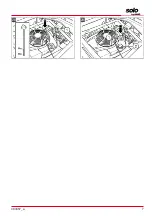
Installing starter battery (24, 25)
The ride-on mower comes with a starter battery.
The starter battery mount is located under the en-
gine cover.
The starter battery is always supplied from the
factory pre-charged.
Summary of Contents for SOLO R7-62.5
Page 3: ...493357_a 3 01 2 a 1 3 02 1 2 3 03 11...
Page 5: ...493357_a 5 14 a 2 1 15 2 2 2 2 1 16 17 18 19 12 1 13 1 2 3...
Page 6: ...6 R7 62 5 R7 63 8 A R7 65 8 HD 22 23 a 24 2 3 25 26 1 0 1 4 bar 27 a 1 20 a 21 a...
Page 7: ...493357_a 7 28 29...
Page 67: ...493357_a 67 6 6 1 26 1 2 1 3 4 1 0 1 4 5 1 0 07 6 2 27 28 1 27 1 27 a 2 28 1 3 MIN MAX 4 5 27...
Page 68: ...RU 68 R7 62 5 R7 63 8 A R7 65 8 HD 6 3 27 29 ROZ 91 1 2 3 27 1 27 a 4 29 1 29 2 5 6 27...
Page 69: ...493357_a 69...
Page 70: ...70 R7 62 5 R7 63 8 A R7 65 8 HD...
Page 71: ...493357_a 71...

