background image

8/00                                                                         3                                                                     33072C

i30SE Direct Vent Gas-Fired Fireplace Insert (Firebox Only)

A Division of Hearth Technologies Inc.

I. LISTINGS AND CODE APPROVALS

U.S. Certification

The i30SE has been tested in accordance with ANSI 

Z21.88-1998 and has been listed by Underwriters Laboratory 

(UL)  for installation and operation as described in these 

Installation and Operating Instructions.  All components are 

A.G.A. or UL safety certified.

Canada Certification

The i30SE has been tested in accordance with CSA 2.33-M98 

and has been listed by UL for installation and operation as 

described in these Installation and Operating Instructions.  All 

components are C.G.A. or C.S.A. safety certified.

Local Codes

Check with your local building code agency prior to installing 

this appliance to ensure compliance with all local codes, includ-

ing the need for permits and follow-up inspections.  This instal-

lation must conform with local codes or, in the absence of 

local codes, with the National Fuel Gas Code, ANSI Z223.1-

latest edition, in the U.S.A. and the CANI-B149-latest edition, 

in Canada.  

Efficiency

The efficiency rating of the appliance is a product thermal effi-

ciency rating determined under continuous operating conditions 

and was determined independently of any installed system.

If any assistance is required during installation please contact 

your local dealer.

II. DESCRIPTION OF THE APPLIANCE SYSTEM


This i30SE system consists of the following:

        1.  Firebox

        2.  Venting System (must be purchased separately)

        3.  Termination (must be purchased separately)

        4.  Blower

        5.  Surround (must be purchased separately)

        6.  Front Face Kit (must be purchased separately)

Please contact your Dealer for details on optional or sepa-

rately purchased parts available for the i30SE.

Note: 

 Illustrations throughout these instructions 

reflect typical installations and are for design pur-

poses only.  Actual installation may vary slightly due 

to individual design preferences.  However, minimum 

and maximum clearances must be maintained at all 

times.
The illustrations and diagrams used throughout these 

installation instructions are not drawn to scale.

Note:  

Operation of a Direct Vent appliance may be 

sporadic in high wind situations.

The i30SE is a Direct Vent Gas-Fired Fireplace Insert Room Heater.  Combustion air is supplied from outside, not from inside the 

house as with other types of appliances.

7 1 R 1

 CERTIFIED FOR CANADA

CERTIFIE POUR LE CANADA

DO NOT REMOVE OR

 COVER THIS LABEL

VENTED GAS FIREPLACE HEATER - NOT FOR USE WITH SOLID FUEL.  FOYER A GAS VENTILE

- NE DOIT PAS ETRE UTILISE AVEC UN COMBUSTIBLE SOLID.  THIS VENTED GAS FIREPLACE HEATER IS NOT FOR USE

WITH AIR FILTER.  - NE PAS UTILISER DE FILTRE A AIR AVEC CE FOYER AU GAZ A EVACUATION.

ALADDIN HEARTH PRODUCTS

A Division of Hearth Technologies Inc.

1445 NORTH HWY.

COLVILLE, WA 99114

SERIAL

NO.  DE SERIE

MODEL       i30SE

MFG.  DATE

MODELE   i30SE

DATE DE FAB.

ANSI Z21.88-1998 CSA 2.33-M98

VENTED GAS FIREPLACE HEATER

FOR USE AT HIGH ALTITUDES.

GAS TYPE

ALTITUDE

MAX. INPUT/DEBIT

MIN. INPUT/DEBIT

OUTPUT

STEADY STATE THERMAL EFF.

MANIFOLD PRESSURE

PRESSION TUBULURE

MIN. INLET PRESSURE FOR THE 

PURPOSE OF INPUT ADJUSTMENT

PRESS. MIN. D'ALIMENTATION

ORIFICE SIZE/DIAM.  INJECTEUR

LESS THAN/MOINS DE 3 AMPERES.,

NATURAL

0-4500 FT/PI

30,000 BTUH

21,000 BTUH

23,400 BTUH

78%

3.5 IN.  W.C.

C.  D'EAU

4.5 IN.  W.C.

C.  D'EAU

.106/2.69 DIA.

115V., 60Hz.

PROPANE

0-4500 FT/PI

28,000 BTUH

22,000 BTUH

22,400 BTUH

80%

10.0 IN.  W.C.

C.  D'EAU

11.0 IN.  W.C.

C.  D'EAU

.063/1.60 DIA.

IN./mm

f i r e - p a r t s . c o m

Summary of Contents for i30SE

Page 1: ...ct Vent Gas Fired Fireplace Insert Room Heater and retained by the homeowner for operating and maintenance instructions A Division of Hearth Technologies Inc Additional components necessary for comple...

Page 2: ...SE AND AT LEAST ANNUALLY BY A QUALIFIED SERVICE PERSON MORE FREQUENT CLEANING MAY BE REQUIRED DUE TO EXCESSIVE LINT FROM CARPETING BEDDING MATERIAL ETC IT IS IMPERATIVE THAT CONTROL COMPARTMENTS BURNE...

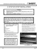
Page 3: ...e contact your Dealer for details on optional or sepa rately purchased parts available for the i30SE Note Illustrations throughout these instructions reflect typical installations and are for design p...

Page 4: ...x 3302 Flex Kit Includes 2 3 x30 Chimney Liner Flex 923GK 3 Direct Vent Chimney Liner Termination Kit Dura Vent product 710 3 Chimney Liner Flex 35 Dura Vent product 980 Vertical Termination Cap with...

Page 5: ...45 North Highway Colville WA 99114 2 1 8 1 1 2 29 20 1 8 8 1 16 6 1 2 13 7 16 IMPORTANT INSTALLATION NOTE The diagram below REPLACES the similar diagram found on page 5 of the Owner s Manual 33072C Pl...

Page 6: ...sistance in deter mining the proper Orifice for your location or refer to ANSI Z223 1 latest edition Appendix F 20 1 4 21 13 1 2 29 1 2 i30SE Minimum Firebox Opening A VENT SYSTEM APPROVALS Approved v...

Page 7: ...s the minimum vertical and corresponding maximum horizontal dimensions of mantels or other combustible projections above the gas fireplace of 12 inches When finishing the fireplace NEVER OBSTRUCT OR M...

Page 8: ...faulty por tion must be repaired or replaced INSTALLATION AND REPAIR SHOULD BE DONE BY A QUALIFIED SERVICE PERSON THE HEATER SHOULD BE INSPECTED BEFORE USE AND AT LEAST ANNUALLY BY A QUALIFIED SERVIC...

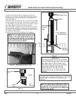
Page 9: ...ipe to the labeled collar on the termination See Figure 5 Figures 6 and 7 show typical installations of the appliance Termination Cap Adaptor Inlet Air Collar Exhaust Collar THIS FIREPLACE HAS BEEN AL...

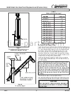
Page 10: ...option shows the air inlet not con nected to the adapter at the top V 14 ft Minimum 40 ft Maximum Termination Cap Adaptor Inlet Air Vent Pipe Exhaust Air Vent Pipe Insulation Note The appliance and i...

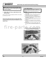
Page 11: ...the top of rear and right front logs See Fig 17 4 Position the center top log into grove on top of rear log Fig 17 5 Position left fork log against rear log and position the forked end of the twig to...

Page 12: ...s exiting the burner pan gas ports will then contact the Rock Wool creating the glowing embers look It is not necessary to use the entire bag of Rock Wool 3 Placing the Vermiculite Sprinkle over the l...

Page 13: ...e unit and secure the latches of the glass frame H Installation of Faces Refer to specific instructions packaged with the face option pur chased for your insert This space left blank for customer inse...

Page 14: ...The Blower temperature sensor switch and junction box are located behind the lower grille To provide the 110 120 VAC 60 HZ are needed at the junction Box Simply plug the 3 prong grounded cord into a...

Page 15: ...inal ends of tester into FAN LH side of the outlet IT SHOULD NOT LIGHT UP If it does light up disconnect power cord from power source Check that only the correct tab is removed Check that the receptac...

Page 16: ...sible shock 3 Check to ensure there are no gas leaks This may be done with a soap and water solution or a gas detector 4 Make sure the glass is sealed and in its proper position Never operate this hea...

Page 17: ...as control knob is at the ON position go to step 6 6 If the pilot light went out during normal use with the gas control knob at the ON position turn the gas control knob to the OFF position REMOVE THE...

Page 18: ...gage the burner and the flames will extinguish Keep the control compartment logs and burner area surround ing the logs clean by vacuuming or brushing at least twice a year AIR SHUTTER AND AIR INLET BA...

Page 19: ...ox Entry on page 6 To clean the glass use a non abrasive mild cleaning solution For example a glass cleaner or for stub born film an oven cleaner Simply apply an ade quate amount to the glass and wipe...

Page 20: ...Relight pilot see page 16 Turn valve to ON Turn switch to ON Check wiring connections at the valve and switch Set thermostat to a lower temperature Check wiring connections and wiring diagram Not heat...

Page 21: ...Male connector 6b 26203 Wire Assembly 7b 25398 ON OFF Rocker Switch 8b 32561 Flex Line 9b 32586 Bulkhead 10b 19837 106 2 69 mm Orifice Natural Gas 17236 063 1 60 mm Orifice L P 11b 33135 Gas Inlet Pi...

Page 22: ...INUED ITEM PART DESCRIPTION 1 32702 Hearth Plate 2 32711 Refractory 3 32684 Burner Assembly 4 32704 Grate Assembly 5 33102 Door Frame Assembly 6 27895 Latch Assembly 7 32599 Termination Plate Assembly...

Page 23: ...__________________ DATE OF PURCHASE ________________ DEALERSHIP WHERE PURCHASED ______________________ DEALERSHIP PHONE NUMBER _______________ COMPONENTS INSTALLED _________________________________ Da...

Page 24: ...r a service call fee and will not be covered The replacement of consumer replaceable items and installation of upgraded component parts do not qualify for a service call fee and will not be covered Th...

Page 25: ...Attention INSTALLER Please return these Operating Installation Instructions to the Consumer A Division of Hearth Technologies Inc 1445 North Highway Colville WA 99114 8 00 33072C fire parts com...

Reviews: