background image

OPERATION

Eagle 20   03/09

Operation Section 4-33

© 2009 Alamo Group Inc.

OPERA

T

ION

9.5 Crossing Ditches and Steep Inclines

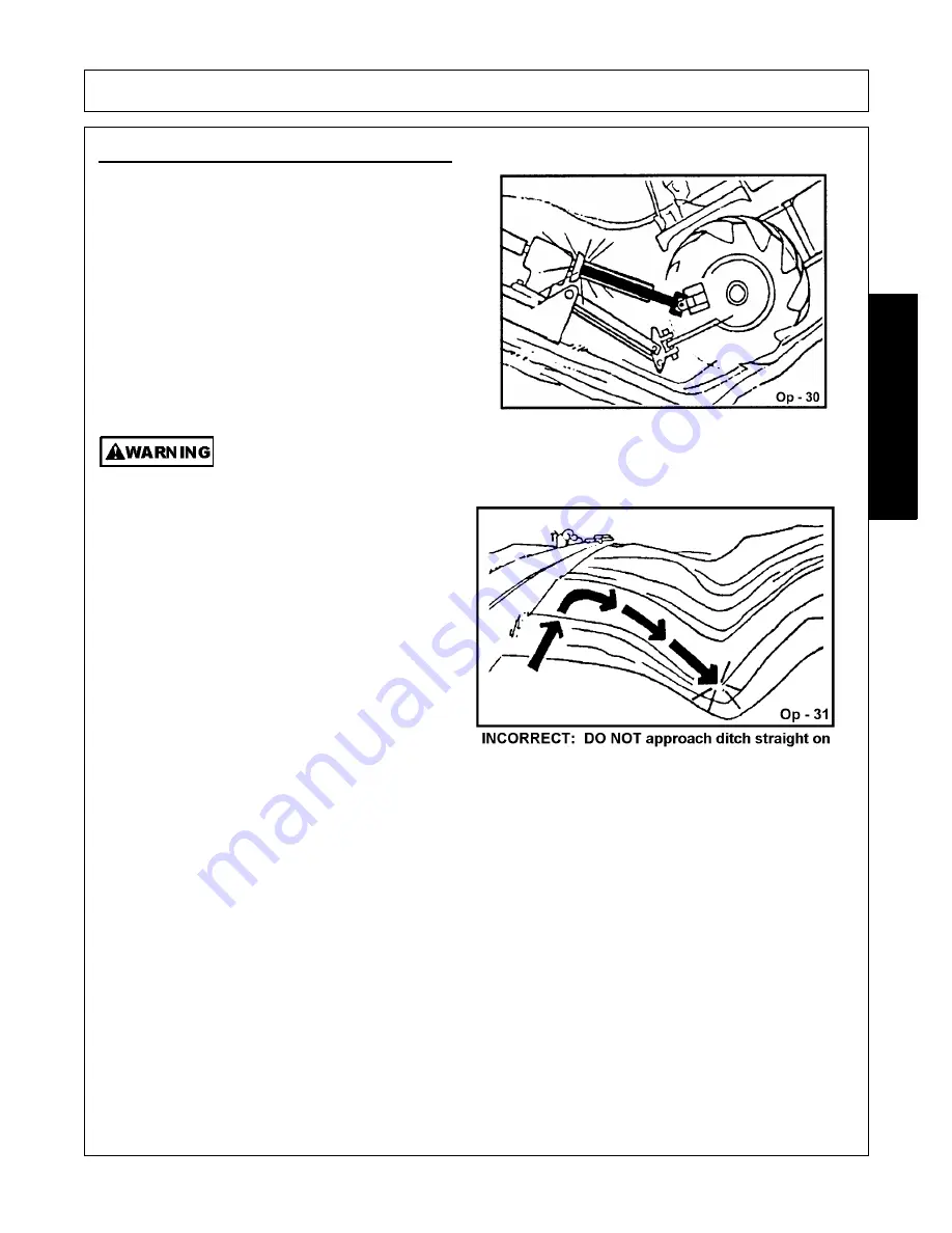
When crossing ditches with steep banks or going up
sharp inclines, it is possible that the main driveline
inner profile will penetrate into the outer housing to its
maximum depth until the assembly becomes solid
(driveline is at its extreme shortest length).  This type
of abusive operation can cause serious damage to
the tractor and mower drive by pushing the PTO into
the tractor and through the support bearings or
downward onto the PTO shaft, breaking it off.

Damage resulting from over-collapse of the driveline’s inner profile and its outer housing
may allow the driveline to come loose from the Tractor which could cause bodily injury to the
operator or bystanders and/or extensive damage to the Tractor or Implement.  

OPS-R-0020

When contronted with an incline or ditch, do not
approach from an angle which is perpendicular or
straight on as damaged to over collapse of the
driveline may occur.

When crossing such terrain, the implement should
be fully lowered for a lower center of gravity and
added stability.  

OPS-R-0021

Summary of Contents for Eagle 14

Page 1: ...s 78155 830 379 1480 FLEX WING MECHANICAL LEVEL LIFT ROTARY MOWER This Operator s Manual is an integral part of the safe operation of this machine and must be maintained with the unit at all times READ UNDERSTAND and FOLLOW the Safety and Operation Instructions contained in this manual before operating the equipment C01 Cover 0 00 ...

Page 2: ... safety equipment properly attached to minimize the chance of accidents BEFORE YOU START Read the safety messages on the implement and shown in your manual Observe the rules of safety and common sense WARRANTY INFORMATION Read and understand the complete Warranty Statement found in this Manual Fill out the Warranty Registration Form in full and return it to within 30 Days Make certain the Serial N...

Page 3: ...ngue Attachment 3 3 Level Rod Assembly 3 3 Wing Section Attachements 3 4 Hose Bracket Attachment 3 4 Center Section 3 5 Level Lift Axle Attachment Figure Asm R 0017 3 5 Axle Adjustment Rod Attachment 3 6 Center Axle Hydraulic Cylinder Attachment 3 6 Wing Section Hydraulic Cylinder Attachment 3 6 TIRES AND WHEELS 3 7 Rubber Stop Attachment 3 8 Baffle Kit Assembly Optional 3 8 Rubber Deflectors Stan...

Page 4: ...g the Tractor and Cutter 4 32 Crossing Ditches and Steep Inclines 4 33 OPERATING THE TRACTOR AND IMPLEMENT 4 34 Foreign Debris Hazards 4 35 Bystanders Passersby Precautions 4 35 Engaging the Power Take Off PTO 4 36 PTO RPM and Ground Speed 4 37 Operating the Mower 4 37 Shutting Down the Implement 4 41 DISCONNECTING THE MOWER FROM THE TRACTOR 4 41 MOWER STORAGE 4 43 TRANSPORTING THE TRACTOR AND IMP...

Page 5: ...TENANCE 5 17 HYDRAULIC HOSES 5 18 SKID SHOES 5 18 STORAGE 5 18 PROPER TORQUE FOR FASTENERS 5 19 Gearbox Tools For Disassembly and Assembly 5 20 Disassembly of Divider Gearbox 5 21 Assembly of WW75 340 5 23 RIGHT ANGLE GEARBOX OUTBOARD ASSEMBLY DISASSEMBLY PROCEDURES 5 31 ...

Page 6: ......

Page 7: ...own this video and presented you a DVD Video when you purchased your mower If you or any mower operator have not seen this video Watch the Video Read this Operator s Manual and Complete the Video Guidebook before operating your new mower If you do not understand any of the instructions included in the video or operator s manual or if you have any questions concerning safety of operation contact yo...

Page 8: ...EMA Mower Operator Safety Video Mower Operator s Manual AEM Mower Operator s Safety Manual Requester Name Phone Requester Address City State Zip Code Mower Model Serial Number Date Purchased DealerSalesperson Dealership Name DealershipLocation Mail to AEM Video Services 1502 E Walnut street Seguin TX 78155 Or Fax to 830 372 9529 Or Email to AEMVideo alamo group com ...

Page 9: ...Safety Section 1 1 2009 Alamo Group Inc SAFETY SECTION ...

Page 10: ... are intended to warn the owner operator of impending hazards and the degree of possible injury faced when operating this equipment Indicates an imminently hazardous situation that if not avoided WILL result in DEATH OR VERY SERIOUS INJURY Indicates an imminently hazardous situation that if not avoided COULD result in DEATH OR SERIOUS INJURY Indicates an imminently hazardous situation that if not ...

Page 11: ...he operator should remain in his seat for 60 seconds after the brake has been set the PTO disengaged the tractor turned off and all evidence of rotation has ceased S3PT 10 Wait a minute Save a life Never crawl under a raised Implement supported solely by the Tractor 3 Point hitch Release of the control lever or mechanical failure will result in the Implement falling and possible injury or death Al...

Page 12: ...or around Tractor or Implement Children can slip or fall off the Equipment and be injured or killed Children can cause the Implement to shift or fall crushing themselves or others SG 25 NEVER use drugs or alcohol immediately before or while operating the Tractor and Implement Drugs and alcohol will affect an operator s alertness and coordination and therefore affect the operator s ability to opera...

Page 13: ...the Tractor and perform repairs before resuming operation Serious injury and possible death could occur from not maintaining this Implement and Tractor in good operating condition SG 36 Avoid contact with hot surfaces of the engine or muffler Use gloves and eye protection when servicing hot components Contact with a hot surface or fluid can cause serious injury from burns or scalding SG 38 Do not ...

Page 14: ...lement s wings Make sure no bystanders are close by or underneath the wings Allow ample clearance around the implement when folding or unfolding the wings Use extreme caution around buildings or overhead power lines S3PT 05 This Implement is wider than the Tractor Be careful when operating or transporting this equipment to prevent the Implement from running into or striking sign posts guard rails ...

Page 15: ...te the Tractor controls from the tractor seat only SG 9 Never allow children or other persons to ride on the Tractor or Implement Falling off can result in serious injury or death SG 10 Never allow children to operate ride on or come close to the Tractor or Implement Usually 16 17 year old children who are mature and responsible can operate the implement with adult supervision if they have read an...

Page 16: ...und you Inadvertent movement of the Tractor or Implement may cause serious injury or death SG 29 In case of mechanical difficulty during operation place the transmission in the park position set the parking brake shut down all power including the PTO and the engine and remove the key Wait until all rotating motion has stopped before dismounting SG 39 Do Not operate this equipment in areas where in...

Page 17: ...y marked and carefully avoided by the operator Stop mowing immediately if blades strike a foreign object Repair all damage and make certain rotor or blade carrier is balanced before resuming mowing SGM 05 Many varied objects such as wire cable rope or chains can become entangled in the operating parts of the mower head These items could then swing outside the housing at greater velocities than the...

Page 18: ...n see Mower Standard Equipment and Specifications DO NOT use this mower to cut vegetation above the Mower s rated capacity or to cut any type of non vegetative material Only operate this Mower on a properly sized and equipped Tractor Operating this Mower in an application for which it is not designed and or operating the Mower with the wrong size Tractor can cause Mower component damage and equipm...

Page 19: ...e final cut more uniform SRM 01 Do Not attempt to raise or lower the implement wing unless the Implement tongue is securely attached to the Tractor drawbar The Implement could tip over and cause equipment damage and possible serious injury or death Raise or Lower the mower wing only while seated in the Tractor operator s seat with the seat belt securely fastened SRM 2 Do not turn so sharp or lift ...

Page 20: ...veline back and forth several times to ensure it is securely attached A driveline not attached correctly to the Tractor PTO shaft could come loose and result in personal injury and damage to the Implement S3PT 17 Before operating the Implement check to make sure the Implement input driveline will not bottom out or become disengaged Bottoming out occurs when the inner shaft penetrates the outer hou...

Page 21: ...rol which could result in property damage or possible injury Do not transport unless 3 Point lift lever is fully raised and in the latched transport position Dropping implement in transport can cause serious damage to the tractor and or Implement and possibly cause the operator or others to be injured or killed S3PT 02 Allow sufficient clearance for the Implement to swing outward while turning Imp...

Page 22: ...sport the Tractor and Implement at the speeds which allow you to properly control the equipment Be aware of the operating conditions Do not operate the Tractor with weak or faulty brakes or worn tires When operating down a hill or on wet or rain slick roads the braking distance increases use extreme care and reduce your speed When operating in traffic always use the Tractor s flashing warning ligh...

Page 23: ...maintain adequate vision of the public roadway and traffic can result in serious injury or even death STI 10 Make sure the PTO shield integral driveline shields and input shields are is installed when using PTO driven equipment Always replace any shield if it is damaged or missing S3PT 8 Relieve hydraulic pressure prior to doing any maintenance or repair work on the Implement Place the Implement o...

Page 24: ...rs and lubrication according to the maintenance section Ensure the unit is properly lubricated as specified in the lubrication schedule and all bolts and nuts are properly torqued Failure to properly service repair and maintain this Implement in good operating condition could cause component failure and possible serious injury or even death SG 35 Use caution and wear protective gloves when handlin...

Page 25: ...parts may reduce mower performance void mower warranties and present a safety hazard Use genuine Alamo Industrial mower parts for economy and safety SPRM 1 SEE YOUR ALAMO DEALER Be sure you have adequate knowledge of the property you will be working on Take time to make yourself aware of any area underground lines or cables Contact with buried lines or cable could result in serious injury or death...

Page 26: ... safe operation Damage to the decals may occur while in shipping use or reconditioning Alamo Industrial cares about the safety of its customers operators and bystanders and will replace the safety decals on this product in the field free of charge Some shipping and handling charges may apply Contact your Alamo Industrial dealer to order replacement decals ...

Page 27: ...STRUCT Notice to Owner 16 D102 1 INSTRUCT PTO to Drawbar Hole Adj 17 D137 1 INSTRUCT CCW Blade Rotation 18 D138 2 1 INSTRUCT CW Blade Roation 19 02960766 2 LOGO Alamo Industrial 20 02977139 2 L NAME Alamo Industrial 21 3 NAME Eagle 20 3 NAME Eagle 14 22 nfs 1 SER PLATE Eagle 20 14 Serial Plate 23 00771283 1 INSTRUCT 5 Year Gearbox Warranty 24 00776031 1 Canister Operator s Manual 25 00778645C 1 Op...

Page 28: ...d English please find someone who knows how to read English P N 00725746 DANGER Stay clear when lowering or raising wings P N 00753840 DANGER Guard Missing Do Not Operate If you see this decal Do Not Operate the mower until the shield has been replaced P N 00756004 DANGER Rotating Driveline Keep Away Contact can cause death P N 00756005 ...

Page 29: ...ng for potential mower hazards Remove or avoid all foreign objects such as wire cable metal objects and all other foreign material Foreign material can be thrown from the mower and cause serious bodily injury to the operator and passerby Do Not let rotating blades contact solid objects like rocks posts curbs or guard rails Operate only if all Guards Deflectors are in place and in good condition Do...

Page 30: ...ing folding and working under raised components Block securely before working under mower Install Weight Box and Weight Min of 700lbs before operating to prevent turning over the center section which can cause SERIOUS BODILY INJURY or DEATH Without weight Do not fold wing Attach transport strap securely to prevent inadvertent dropping from the transport position and possible CRUSHING INJURY OR DEA...

Page 31: ...ily Injury Use 1000 RPM PTO Speed Only P N D114 Slow Moving Vehicle Decal Keep SMV reflector clean and visible DO NOT transport or operate without the SMV P N 03200347 Red Reflector Keep reflectors clean and visible P N 1458392 Amber Reflector Keep reflectors clean and visible P N 1458393 ...

Page 32: ...Y Operator s Manual with repair parts and warranty was attached to this implement during final inspection P N 00763977 IMPORTANT Required For Jackshaft Unit Suggested for standard shaft P N D102 Blade Rotation Counter Clockwise P N D137 Blade Rotation Clockwise P N D138 ...

Page 33: ...FETY Eagle 20 03 09 Safety Section 1 25 2009 Alamo Group Inc SAFETY NAME LOGO Alamo Industrial P N 02960766 Name LOGO Alamo Industrial P N 00757139 NAME LOGO EAGLE 20 EAGLE 20 NAME LOGO EAGLE 14 EAGLE 14 ...

Page 34: ...Section 1 26 2009 Alamo Group Inc SAFETY INFORMATION 5 Year Gearbox Warranty P N 00771283 Read Operator s Manual The operator s manual is located inside this canister If the manual is missing order one from your dealer P N 00776031 ...

Page 35: ...SAFETY Eagle 20 03 09 Safety Section 1 27 2009 Alamo Group Inc SAFETY Multi Hazard Decal Sheet P N 00749117 ...

Page 36: ...ne Safety P N 00773723 WARNING DO NOT transport at speeds higher than 20 mph Only transport behind a properly sized and equipped tractor P N 00777394 WARNING Explosion Hazard Release all air pressure in tire before loosening bolts P N 1006348 WARNING Jack Maximum Capacity 3 200 lbs Side Load 2 000 lbs P N D482 ...

Page 37: ...e operation and servicing of all equipment with which the employee is or will be involved Employer Responsibilities To ensure employee safety during Tractor and Implement operation it is the employer s responsibility to 1 Train the employee in the proper and safe operation of the Tractor and Implement 2 Require that the employee read and fully understand the Tractor and Implement Operator s manual...

Page 38: ......

Page 39: ......

Page 40: ......

Page 41: ......

Page 42: ......

Page 43: ......

Page 44: ......

Page 45: ......

Page 46: ......

Page 47: ......

Page 48: ......

Page 49: ......

Page 50: ......

Page 51: ......

Page 52: ......

Page 53: ......

Page 54: ......

Page 55: ......

Page 56: ......

Page 57: ......

Page 58: ......

Page 59: ......

Page 60: ......

Page 61: ......

Page 62: ......

Page 63: ......

Page 64: ......

Page 65: ......

Page 66: ......

Page 67: ......

Page 68: ......

Page 69: ......

Page 70: ......

Page 71: ......

Page 72: ......

Page 73: ......

Page 74: ......

Page 75: ......

Page 76: ......

Page 77: ......

Page 78: ......

Page 79: ......

Page 80: ......

Page 81: ......

Page 82: ......

Page 83: ...Introduction Section 2 1 2009 Alamo Group Inc INTRODUCTION SECTION ...

Page 84: ...rotect the operator passerby livestock and property from thrown objects deflectors single chain guards and double chainguards Shielding should be selected based on the intended use of the mower Double chainguards or deflectors should be used for highway right of way parks or greenbelt mowing or all other mowing where human dwellings vehicles or livestock could be within 300 feet of the mower Chain...

Page 85: ...speed either 540 or 1000 RPM Should you desire to change PTO input speed contact your local Alamo Industrial dealer who will assist you in performing the necessary modifications A different Driveline and set of Gears are required This machine is designed for use with tractors rated 75 HP 45kW to 140 HP 103kW When ordering parts for the Gearboxes and the Drivelines be sure to specify the PTO speed ...

Page 86: ...nt 2 Fill out the Warranty Card in full Be sure to answer all questions including the Serial Number of the implement Mail within 30 days of delivery date of this implement NOTE Warranties are honored only if completed Owner Registration and Warranty forms are received by Alamo Group within thirty days of delivery of the implement 3 Record the Blade Model and Serial Numbers on the Warranty page at ...

Page 87: ...Assembly Section 3 1 2009 Alamo Group Inc ASSEMBLY SECTION ...

Page 88: ...components are aligned and loosely assembled before tightening hardware Refer to Torque Chart when tightening hardware Position Center Section on a flat surface Elevate approximately 10 inches from ground to permit the installation of Wing Sections Blade Carrier and Blades Do not install Blades or do any work under the Cutter sections unless the section s are safely and securely blocked or latched...

Page 89: ...Chain 14 by looping it through the hole on the tongue and the largest link on the chain Make certain to securely attach the hook end to the tractor when transporting Level Rod Assembly Lay Long Level Rods 10 on Center Section frame tube and attach to Tongue with Level Rod Pins 11 washers 12 and cotter pins 13 shown in FIGURE Asm R 0013 above Attach Jam Nuts 15 and Adjusting Nuts 16 to the Long Lev...

Page 90: ...ock the Wing Sections in place with the Hinge Pins Insert 5 16 x 1 1 2 bolt 3 and locknut 4 at the end of each of the Hinge Pins and tighten securely FIGURE Asm R 0015 Hose Bracket Attachment Hose Brackets are attached in the front and rear of the cutter The Front Hose Bracket 1 attaches to the Hose Bracket Mounting on the right side of the tongue mount 2 with Bolt 3 Washer 4 and Nut 5 The Rear Ho...

Page 91: ... the Wing Pins 10 Bolts 4 and Nuts 5 Install the Grease Fittings 11 on the ends of the Wing Pins and on the bearings of the Center Section Axle 1 To attach an axle to a section 1 Align the axle tube pivots in the hinge area on the section 2 Insert the Pin thru the hinge plate the tube pivot and make it come to rest on the other hinge plate 3 Turn the Pin to align to the bolt hole as necessary and ...

Page 92: ...achment Mount the 14 stroke Hydraulic Cylinder butt clevis to the upright lugs on the Center Section and the rod end to lugs on wing Make sure the ports of the Hydraulic Cylinder are facing upwards Keep the ports capped until the hoses are attached to the tractor and are ready to attach to the cylinder ports Make certain that the Restrictor A in Image Asm R 0019 is installed properly on the gland ...

Page 93: ...ypes of tires that can be used on this cutter DO NOT USE ANY OTHER TYPE OF TIRE OR WHEEL such as automotive tires and rims DO NOT EXCEED THE MAXIMUM SPEED FOR EACH TYPE OF TIRE As excessive speed can cause damage to the machine tire and wheel When installing Sectional Tires and Wheels note the direction of travel and the curvature of rubber segments in the tire and install as shown in FIGURE 10 Do...

Page 94: ...1 2 capscrew 2 inserted thru the stop 3 spring 4 and locknut 5 Image AsmP R 0006 Baffle Kit Assembly Optional The Center Baffle 2 is attached to the Center Sect Zion with Bolts 7 Washers 8 and Locknuts 3 as shown in FIGURE Asm R 0058 The Wing Baffles 4 RH 5 LH are attached to the wings with Bolts 7 Washers 8 Flatwasher 6 and Locknuts 3 as shown in FIGURE Asm R 0094 ...

Page 95: ... Asm R 0059 Attach the Front Wing Deflector Bars 3 and Front Wing Deflector 4 to the wing sections with the bolts 5 lockwashers 7 and flatwashers 6 FIGURE Asm R 0059 Fasten the Center Rear Rubber Deflector 1 and Rear Center Section Deflector Bar to the Center Section with bolts 5 flatwashers 7 and locknut 8 Attach the Rear Wing Rubber Deflector 3 and Rear Wing Deflector Bar 4 with bolts 5 lockwash...

Page 96: ...eplacing missing or worn sections or by replacing completely when worn or damaged The placement of the Chain Guards corresponds to the Rubber Deflector Attachment with the exception of the Front Center Section see FIGURE Asm R 0122 0133 Attach all Chain Guards with bolts and locknuts specified in the parts list Single Chain Guards Attach Chain bracket 1 to deck with 1 2 x 1 1 2 bolt 5 washer 3 and...

Page 97: ...0028 Driveline Attachment Remove Wing Nuts holding Divider Gearbox Shield and raise Shield Remove any tape from Gearbox shafts Attach the Torque Limiter Clamp Yoke end of the Wing Driveline to the Divider Gearbox Tighten bolts evenly to their proper torque FIGURE Asm R 0020 Attach opposite end of driveline to blade Gearbox shaft Attach using hardware provided Move yoke limiter group back and forth...

Page 98: ...aft Regularly check the driveline yoke to ensure a tight connection To remove the yoke remove the connecting cone and pull yoke off the shaft If the cone cannot be easily removed by hand drive it out from the other side using a hammer and punch NOTE The clamping cone is serviced only as a complete assembly Do not attempt to disassemble the clamping cone Canopy Shields After final adjustment attach...

Page 99: ...pment which includes fender bracket fittings hoses and shield required to mount valve Refer to Parts List Section 6 36 Install Restrictors in Gland Ports in Wing Cylinders To install the hydraulics from the Cutter to the Control Valve connect the Center Axle Lift Cylinder Hose to the Right Port on the Hydraulic Valve Connect the Right Wing Folding Cylinder Hose to the Center Port of the Hydraulic ...

Page 100: ......

Page 101: ...Operation Section 4 1 2009 Alamo Group Inc OPERATION SECTION ...

Page 102: ...in explaining the operation of a rotary mower and are not necessarily of an EAGLE 20 14 cutter Some pictures may show shields removed for purposes of clarity NEVER OPERATE this implement without all shields in place and in good operational condition The operator must be familiar with the mower and tractor operation and all associated safety practices before operating the mower and tractor Proper o...

Page 103: ...IONAL EQUIPMENT Driveline Size Single or Double Front Rear Chain Guards Main CAT 5 HD 540 or 1000 RPM Wings CAT 6 HD Constant Velocity or Non C V Main Driveline Driveline Limited Warranty 2 Year Pan or Bar Blade Carriers Driveline Protection Slip Clutch Laminated Foam Filled Used Airplane Used Deck Thickness 10 Ga Plane Implement or Recapped Used Airplane Side Skirts Replaceable 1 4 x10 1 2 Tire o...

Page 104: ...operating instructions to the operator Safe operation of equipment requires that the operator wear approved Personal Protective Equipment PPE for the job conditions when attaching operating servicing and repairing the equipment PPE is designed to provide operator protection and includes the following safety wear PERSONAL PROTECTIVE EQUIPMENT PPE Protective Eye Glasses Goggles or Face Shield Hard H...

Page 105: ...End Weights As needed to maintain 20 weight on front axle Power Take Off 540 RPM 6 spline or 1000 RPM 21 spline 1 3 8 diameter output shaft depending on mower operating speed For other PTO Drawbar Category Combinations see your Tractor specifications Drawbar Category Tractor Horsepower PTO TYPE Drawbar Length I 75 1 3 8 21 16 II 75 1 3 4 20 20 III 75 1 3 8 6 14 2 1 ROPS and Seat Belt The tractor m...

Page 106: ...1000 RPM mowers set the drawbar length at 16 for 21 spline 1 3 8 mowers and at 20 for 1 3 4 20 spline mowers Ensure that the drawbar is rated to carry the tongue weight of the mower Pintle Hook Hitch Optional Equipment Drawbar length must be modified to obtain dimension A CV Driveline 17 2 2 2 Tractor Safety Devices If transporting or operating the tractor and implement near a public roadway the t...

Page 107: ...eed of 540 or 1000 RPM Most tractors operate at either 540 or a combination of 540 and 1000 RPM PTO speeds The operating speed of the mower and tractor can be determined by the number of splines on the driveline yoke and PTO output shaft Those operating at 540 RPM will have a 6 spline shaft and those operating at 1000 RPM will have a 21 spline shaft Note Refer to the tractor owner s manual for ins...

Page 108: ... Never allow children to operate ride on or come close to the Tractor or Implement Usually 16 17 year old children who are mature and responsible can operate the implement with adult supervision if they have read and understand the Operator s Manuals been trained in proper operation of the tractor and Implement and are physically large enough to reach and operate the controls easily SG 11 Never al...

Page 109: ... hydraulic remote control levers Before starting the tractor ensure the following Conduct all pre start operation inspection and service according to the tractor operator s manual Make sure all guards shields and other safety devices are securely in place The parking brake is on The PTO control lever is disengaged The 3 point hitch control lever is in the lowered position The hydraulic remote cont...

Page 110: ... the bottom of drawbar and bot tom lip of clevis to fill open space Insert a 1 diameter grade 5 or 8 bolt 3 through clevis and drawbar and retain in position with a 1 locknut 4 Tighten the locknut securely but do not over tighten which could spring or break the clevis NEVER attach mower to the tractor with a pin not having a nut 5 Securely attach the mower safety chain to the tractor drawbar or dr...

Page 111: ...pment Ensure the valve matches the hydraulic operating system of the tractor open or closed center Refer to the Assembly Section for additional information on equipping the tractor with a 3 spool control valve Mount the valve bank to a tractor fender or other accessible location Connect valve bank inlet and outlet lines to outlets of the same tractor hydraulic port Connect the mower hydraulics to ...

Page 112: ...position and repeat process a second time Ensure wings are entirely supported by the cylinders before removing the transport braces NEVER drive out bar pins and NEVER remove braces that have tension on them 6 SETTING THE MOWER Properly setting the cutting height is essential for efficient and safe operation A properly set mower will make a more uniform cut distribute clippings more evenly require ...

Page 113: ...wer when making adjustments To adjust rod length loosen jamnut and screw turnbuckles To lower the front lengthen the rods and to raise the front shorten the rods DO NOT unscrew turnbuckles to the point that either rod threaded ends becomes disconnected which will cause the mower to fall Re tighten jamnuts when deck is leveled Alternate adjustments between rods and adjust at equal lengths to mainta...

Page 114: ...the tractor In addition a more even distribution of the clippings from the rear of the mower will be achieved with this deck pitch Adjust the leveling rods linking the tongue to the rear axle until the front of the mower is at least 3 4 lower in the front that than the rear To lower the front lengthen the leveling rods and to raise the front shorten the leveling rods IMPORTANT Adjust the leveling ...

Page 115: ...d and in good workable condition Mower sections or Wings are running close to and parallel to the ground without exposed Blades Passersby are outside the existing thrown object zone All areas have been thoroughly inspected and all foreign material such as rocks cans glass and general debris has been removed NOTE Where there are grass and weeds high enough to hide debris that could be struck by the...

Page 116: ...ing collar and position the yoke until the locking collar balls are seated onto the PTO shaft Push and pull the driveline back and forth several times to ensure a secure attachment OPS R 0003_A When attaching the Implement input driveline to the Tractor PTO it is important that the connecting yoke spring activated locking collar slides freely and the locking balls are seated securely in the groove...

Page 117: ...r local dealer or tech service for proper directions OPS R 0004_B Engagement Check Procedure With the driveline attached position the mower to the point where the telescoping driveline is at its maximum extension Completely shut down the tractor and secure in position Mark the inner driveline shield 1 8 from the end of the outer shield Disconnect the driveline from the tractor and separate the two...

Page 118: ... a hard left turn until there is approximately a 1 clearance between the left rear tractor tire and mower frame or tongue Stop and completely shut down the tractor Place the tractor in Park and apply the Parking Brake before dismounting Check the CV joint at this maximum turning radius by holding the driveline yoke above the PTO shaft and then angle the CV joint to its maximum angle A minimum diff...

Page 119: ...ble down time and repair cost can be avoided OPS U 0029 Always disconnect the main PTO Driveline from the Tractor before performing service on the Implement Never work on the Implement with the tractor PTO driveline connected and running Rotating Parts Blades or Drivelines could turn without warning and cause immediate entanglement injury or death S3PT 11 DO NOT allow any person under a folded win...

Page 120: ... OPS U 0030 8 2 Mower Pre Operation Inspection Service Before each mower use a complete inspection and service is required to ensure the mower is in a good and safe working condition Damaged and or broken parts should be repaired and or replaced immediately To ensure the mower is ready for operation conduct the following OPS R 0007 All Safety Shields Guards and Safety devices including but not lim...

Page 121: ... and illegible decals OPS U 0011 Ensure the mower hitch is securely attached to the tractor drawbar with a proper size bolt and secured nut Ensure that a properly rated safety tow chain is equipped securing the mower to the tractor Check that the main driveline is securely attached to the tractor and the clamping cone is seated in the groove of the PTO shaft Ensure the divider drivelines are secur...

Page 122: ...cified in the maintenance section Inspect each gearbox oil level and replenish if needed A low oil level is a warning sign that the gearbox may be cracked or its seal is dam aged and needs to be replaced Ensure all gearbox vents are in place and free from clogs OPS R 0011_B Inspect blades and blade bolts for looseness and excessive wear Make sure the mower is securely blocked up before crawling be...

Page 123: ... ports IMPORTANT DO NOT use your hands to check for oil leaks Use a piece of heavy paper or cardboard to check for hydrau lic oil leaks OPS R 0013_A Ensure that the mower is equipped and secured with wing transport locks Check the condition of the wing hinge pins Check the condition of the mower axle suspen sion spring Inspect mower tire condition wheel bearings and lug nut torque OPS R 0014_A Bef...

Page 124: ...OPERATION Eagle 20 03 09 Operation Section 4 24 2009 Alamo Group Inc OPERATION 8 3 Cutting Component Inspection Inspect blade pan and blade assembly for the following OPS U 0031 ...

Page 125: ...shape or Any cracks are visible or Deep gouges in the blade s surface are persent or Gouges or chipped areas in the cutting edge are larger than 1 2 12 7mm or The material on the leading edge has been worn away by more than 1 2 12 7mm Failure to replace abnormally worn blades may lead to catastrophic failure of the blades and ejection of the broken part with tremendous force which may cause seriou...

Page 126: ...DE BOLTS on the Blades IMMEDIATELY if either blade bolts has Visible cracks or If the recessed area on blade bolt is worn off or If Blade Bolt has gouges or chipped areas Failure to replace abnormally worn blade bolts may lead to catastrophic failure of the blades and ejection of the broken part which may cause serious bodily injury or death Always replace Blade Bolts with new bolts whenever repla...

Page 127: ...SMV Sign is clean and visible The tires are in good condition with proper pressure The wheel lug bolts are tight The tractor brakes are in good condition The steering linkage is in good condition There are no visible oil leaks The hydraulic controls function properly The ROPS or ROBS Cab is in good condition The seatbelt is in place and in good condition The 3 point hitch is in good condition The ...

Page 128: ...afety decals are in place and legible The tongue hitch connection bolts pins are tight There are no cracks in tongue or hitch The tow chain is secured to the tractor mower The hydraulic cylinders pins are tight There are no leaking or damaged hoses The mower deck is clear of cut grass and debris Chain guards deflectors are in place in good condition Driveline gearbox shields are in good condition ...

Page 129: ...ng and brakes are in good condition and operate properly Before transporting the Tractor and Implement determine the proper transport speeds for you and the equipment Make sure you abide by the following rules Test the tractor at a slow speed and increase the speed slowly Apply the Brakes smoothly to determine the stopping characteristics of the Tractor and Implement As you increase the speed of t...

Page 130: ... or limit the tractor from turning During normal cutting conditions locking the differential provides no benefit and should not be used OPS U 0013 Be aware of the operating conditions Do not operate the Tractor with weak or faulty brakes When operating down a hill or on wet or rain slick roads the braking distance increases use extreme care and reduce your speed in these conditions When operating ...

Page 131: ...ment to overturn the Tractor and vice versa resulting in serious injury or even death Never fold wings on a hillside the Implement may overturn STI 02 Operating Position To lower the wings remove the transport lock braces and secure braces on storage bracket DO NOT drive out transport brace pins The wing cylinder may need to be retracted to remove tension for brace removal After removing brace bar...

Page 132: ...he control lever in the transport detent position to prevent damage to the mower driveline and tongue when turning Perform turns with the tractor and mower at slow speeds to determine how the tractor with an attached mower handles a turn Determine the safe speed to maintain proper control of the tractor when making turns When turning with a towed implement the overall working length of the unit is...

Page 133: ...ing the PTO into the tractor and through the support bearings or downward onto the PTO shaft breaking it off Damage resulting from over collapse of the driveline s inner profile and its outer housing may allow the driveline to come loose from the Tractor which could cause bodily injury to the operator or bystanders and or extensive damage to the Tractor or Implement OPS R 0020 When contronted with...

Page 134: ...E TRACTOR AND IMPLEMENT AND ALL CONTROLS BEFORE ATTEMPTING TO OPERATE The operator must read and understand the Safety and Operation Sections of the implement and tractor operator s manuals These manuals must be read and explained to any operator who cannot read Never allow someone to operate the implement and tractor without complete operating instructions Before starting any operation the operat...

Page 135: ...t once Immediately idle the engine speed and disengage the PTO Wait for all mower rotating motion to stop then raise the mower and move the tractor and implement off the object Inspect the area and remove or mark the location of the debris Inspect the condition of the mower and make any needed repairs immediately Make sure the blades are not damaged and the carrier is balanced before resuming oper...

Page 136: ...ain spread cut material better reduce streaking and make the final cut more uniform SRM 01 10 3 Engaging the Power Take Off PTO Before engaging the PTO make certain that the area is clear of bystanders and passersby The implement must be completely lowered and the deck positioned at a safe operating height NEVER engage the PTO with the implement in the raised position Set the tractor engine speed ...

Page 137: ...erate and control the tractor and mower The correct mowing speed depends on terrain condition and grass type density and height of cut Normal ground speed range is from 2 to 5 mph 3 8 kph Use slow mowing speeds when operating on or near steep slopes ditches drop offs overhead obstructions power lines or when debris and foreign objects are to be avoided SGM 07 10 5 Operating the Mower The mower is ...

Page 138: ...e no persons behind the mower and use extreme care when mowing in reverse Mow only at a slow ground speed where you can safely operate and control the tractor and mower Never mow an area that you have not inspected and removed debris or foreign material SGM 08 Follow these guidelines to reduce the risk of equipment and grass fires while operating servicing and repairing the Mower and Tractor Equip...

Page 139: ...he tractor PTO shaft and could cause extensive mechanical damage to the mower and tractor If the mower is operated in conditions that require frequent sharp turning the mower should be equipped with a Constant Velocity driveline CV joints enable the tractor PTO shaft and mower driveline to be angled safely up to 80 degrees with no damage to the mower or driveline OPS R 0027 Do not let the Blades t...

Page 140: ...l or dirt which can cause rapid blade wear and extremely severe shock loads on the drivetrain resulting in rapid wear or damage to these components Blades contacting the ground may cause objects to be thrown out from under the mower deck Always avoid operating the mower at a height or position which may cause the blades to contact the ground Cutting into the berm or edge of the ditch will cause ab...

Page 141: ...o a complete stop before exiting the tractor OPS U 0016 11 DISCONNECTING THE MOWER FROM THE TRACTOR Before disconnecting the mower the PTO must be disengaged and blade rotation at a complete stop Move the mower to a level storage location and lower the center section and both wings to the ground If the mower will be stored with the wings in the raised position install both wing transport lock brac...

Page 142: ...ing on the tractor drawbar and is supported solely by the jack The jack should be in a near vertical position with the ground and can be adjusted by loosening the positioning nut and moving the jack up to 15 degrees in each direction Also make sure that the jack foot is securely resting at ground level or securely supported by a block before raising the mower Once the mower tongue is being support...

Page 143: ...spray touch up enamel where necessary to prevent rust and maintain the appearance of the mower It is critical that driveline clutches slip when an obstacle or heavy load is encountered to avoid mower and or tractor damage If the mower sits outside for an extended period of time or is exposed to rain and or humid air the clutch lining plates must be inspected to ensure they are not frozen together ...

Page 144: ... secure its end to the mower deck The mower can then be raised to the maximum lift height OPS R 0033 If the tractor s hydraulic pump is not independent of the tractor PTO or if the tractor PTO has to be run to have hydraulic power disconnect the mower driveline from the tractor PTO output shaft Secure the driveline to the mower deck to prevent driveline damage or loss during transport OPS R 0034 B...

Page 145: ...or must be equipped with all required safety warning features including a SMV emblem and flashing warning lights to alert drivers of the tractor s presence Remember that roadways are primarily designed for automotive drivers and most drivers will not be looking out for you therefore you must look out for them Check your side view mirrors frequently and remember that vehicles will approach quickly ...

Page 146: ...a slow speed SMV signs are a triangular bright orange with reflective red trim for both easy day and night visibility Make sure the SMV sign is clean and visible from the rear of the unit before transporting the tractor and implement on a public roadway Replace the SMV emblem if faded damaged or no longer reflective OPS U 0020 Make sure that all tractor flashing warning lights headlights and brake...

Page 147: ... and implement on public roads Use caution and reduce speed if other vehicles or pedestrians are in the area OPS U 0022 Reduce speed before turning or applying the brakes Ensure that both brake pedals are locked together when operating on public roads OPS U 0023 13 3 Hauling the Tractor and Implement Before transporting a loaded tractor and implement measure the height and width dimensions and gro...

Page 148: ... so that when tightened the chains are pulling downward and against themselves Carefully tighten the securing chains or other fasteners using boomers or binders to apply maximum tension Use extreme care when attaching and removing the securing devices as the extreme tension involved when released has the potential to inflict serious injury While hauling the tractor and implement make occasional st...

Page 149: ...ly Remove hub check tapered spline seated on shaft shaft clean and replace New Blade or bolts matched Replace blades or bolts in sets Drivelines not phased Replace Drivelines Gearbox Overheating Low on lubricant Fill to level plug Improper type lubricant Replace with proper lubricant Excessive trash build up Remove trash around gear box Bearing or gears set up improperly Consult your dealer Gearbo...

Page 150: ...oke collars normal Piston O ring worn Replace piston O ring Cylinder wall scored or pitted Replace cylinder Wrong piston ring on piston Use correct piston rings Not Cutting Clean Blades dull Sharpen or replace blades Blade rotation incorrect Use correct blade for carrier rotation Carrier RPM too low Use correct PTO speed and check for correct gear box ratio Cutter not level Adjust machine Tires ma...

Page 151: ...Maintenance Section 5 1 2009 Alamo Group Inc MAINTENANCE SECTION ...

Page 152: ...making adjustments Lubrication Do not let excess grease collect on or around parts particularly when operating in sandy areas The illustrations below shows lubrication points The chart gives the frequency of lubrication in hours based on normal operating conditions Severe or unusual conditions may require more frequent lubrication Figure MntP R 0003 Use Multi Purpose Gear Oil P N 00786250 for all ...

Page 153: ...MAINTENANCE Eagle 20 03 09 Maintenance Section 5 3 2009 Alamo Group Inc MAINTENANCE ...

Page 154: ... securely to cutter and tractor CENTER WING GEARBOXES The Gearboxes have been filled with lubricant to the Test Plug Level prior to shipment However you should check the oil level at Test Plug before operating and frequently thereafter The gearbox should not require additional lubricant unless the box is cracked or a seal is leaking It is recommended that the vent plug be checked after every 8 to ...

Page 155: ...ocated on the right side of the input shaft The filler pressure relief Plug is on top of the Gearbox FIGURE MntP R 0005 Do not over fill If Gearboxes are filled above Test Plug Level pressure under working conditions may cause the Grease Seals to leak Recommended lubricant is a NLGI 000 EP Grease P N 00769030 for on quart for divider gearbox ...

Page 156: ...The CV Joint is located at the end of the Main Driveline The U Joint and CV Joint assemblies are accessible by rotating the Driveline Safety Shield until the hole in the Shield matches up with the Grease Fitting Use 2 Bearing Grease for lubrication Inspect the U Joint for wear by holding the shaft on one side of the U Joint while trying to rotate the shaft on the other side of the U Joint If there...

Page 157: ...0038 Turn inner cone to assembly position and remove half shield Remove bearing ring MNT R 0038 To assemble outer CV driveline grease yoke groove and inner profile tube Attach bearing ring on groove with recesses facing profile tube Slide on half shield with cone Turn cone until it engages correctly Tighten locking screws Grease bearing groove in double yoke Insert bearing ring Slide guard cone fo...

Page 158: ... the two shield bearings per half shaft by prying the head of the bearings up with a screwdriver and pulling them out with pliers Figure MntP R 0012 Grasp the Yoke and shield tube and pull shaft from the shield Figure MntP R 0013 Grease the shield bearing grooves on the yokes and the inner telescoping member before assembly ...

Page 159: ... MntP R 0015 Slide the shield tube assembly over the shaft so that the bearing holes in the shield align with the shield bearing groove on the yoke Figure MntP R 0016 Install two shield bearings per half shaft by pushing one bearing in each bearing hole The shield bearings should be installed in the direction of the shaft rotation relative to the shields Figure MntP R 0017 Attach safety decal as n...

Page 160: ...ce strike top arm of unsupported yoke to drive the top cup up Repeat on opposite side 3 If you cannot grip the loosened cap per Step 4 use a pointed tool to tip a needle them repeat Step 2 4 Grip loosened cup in vise strike yoke arm to drive yoke off cup Repeat on opposite cup 5 Support cross in loose vise and strike yoke arm Repeat Step 4 to remove remaining two cups ...

Page 161: ...INTENANCE TO REASSEMBLE UNIVERSAL JOINT 1 Smear grease into bearings and check for dirt CAUTION Make sure all needle bearings are seated properly 2 Insert cup and cross Drive in with spacer 3 Insert snap ring 4 Insert second cup and hold cross into cup Drive cup flush with arm ...

Page 162: ... 5 12 2009 Alamo Group Inc MAINTENANCE 5 Drive cup down with spacer and insert snap ring 6 To loosen cross strike yoke arm and check cross for free rotation 7 Position second yoke on cross Repeat Steps 2 to 6 Grease Kit after assembly is completed ...

Page 163: ...LLY AND CAUSE BODILY INJURY OR DEATH Inspect Blades daily for abnormal wear If Blades have a notch worn into the leading edge at the lower bend more than a 1 2 DEEP FIGURE 12 due to running in gravel and or the ground REPLACE BOTH BLADES ON THAT CARRIER IMMEDIATELY Failure to replace such abnormally worn blades may lead to catastrophic failure of the blade and ejection of the broken part with trem...

Page 164: ...uated even with the engine stopped or in the event of hose failure etc Always use a secure support for equipment which must be serviced while in the raised position NOTE Replace Blades in pairs after no more than 1 2 notch wear BLADE REMOVAL To remove blades for sharpening or replacement remove the cover plate on deck of cutter near each gear box Remove locknut from blade bolt note These are Left ...

Page 165: ... snug slip fit If the blade bolt fit appears to be loose or sloppy measure the square hole in bushing If the bottom of the square hole is 1 16 or greater than the square shoulder of the new blade bolt the bushings should be replaced Bushings can be removed by cutting bushing head where it is welded to carrier bar Once head is removed bushing can be pressed out of bar Clean and grind top of blade b...

Page 166: ...igned to slip absorb the shock load and protect the drivelines of the mower After the first hour of operation the slip clutches should be checked for overheating After this first check inspect weekly or anytime there is overheating To adjust the slip clutch tighten the spring bolts 1 8 maximum turn at a time See Figure Mnt R 0018 for minimum dimension DO NOT tighten springs beyond 1 15 32 length f...

Page 167: ...on pressure is 50 PSI minimum inflation pressure is 20 PSI Inflate ribbed implement tires to manufacturer rated PSI as shown on the tire sidewall SEASONAL TORQUE LIMITER MAINTENANCE It is important that the clutches slip when an obstacle or load heavier than the clutch setting is encountered Therefore if the machine sits outside longer than 30 days and is exposed to rain and or humid air it is imp...

Page 168: ...ife Premature wear can be caused by the cutter Wing sections being set too low which allows the Wing Skid Shoes to drag on the ground Dragging the Skid Shoes on the ground or running the Skid Shoes into solid objects can contribute to early frame failure on the cutter Replace worn Skid Shoes as required STORAGE Your rotary cutter represents an investment from which you should get the greatest poss...

Page 169: ... the grade of bolts and the proper torque except when specific torque values are assigned in manual text RECOMMENDED TORQUE IN FOOT POUNDS UNLESS OTHERWISE STATED IN THE MANUAL NOTE These values apply to fasteners as received from supplier dry or when lubricated with normal engine oil They do not apply if special graphited or molydisulphide greases or other extreme pressure lubricants are used Thi...

Page 170: ...AND SUB ASSEMBLIES TO PREVENT INJURIES TO HANDS AND FEET DUE TO INADVERTENT DROPPING OR FALLING OVER ALWAYS WEAR SAFETY GLASSES AND GLOVES TO PREVENT EYE AND HAND INJURY WHEN CHISELING OR HAMMERING ON METAL COMPONENTS HARDENED METAL WILL CHIP UN EXPECTEDLY AN ASSEMBLED GEARBOX IS QUITE HEAVY USE A HOIST OR GET HELP TO HANDLE THEM SAFELY LIFT CAREFULLY AND PROPERLY USING YOUR LEGS TO LIFT NOT YOUR ...

Page 171: ...rom both Cap Hubs using a 14mm socket FIGURE Mnt R 0048 Remove the Hub Assemblies and gaskets from the Main Housing FIGURE Mnt R 0048 STEP 2 Remove the Hub Assembly from the vise and place it on a solid surface with the Gear in an upright position Using a Hammer tap this Gear downward until the Adjusting Nuts fully exposed Remove the Cotter Pin Remove the Adjusting Nut FIGURE Mnt R 0049 ...

Page 172: ...Shaft has cleared the Bearing it can be fully removed from the Hub Assembly The remaining Bearings and Bearing Cups can be removed by conventional means FIGURE Mnt R 0050 STEP 4 Remove all eight Bolts from Input Cap using a 14mm Socket Then using a Hammer tap the Output end of the Input Shaft This will loosen the input Cap and allow the removal of the complete Input Shaft Assembly FIGURE Mnt R 005...

Page 173: ...be removed by conventional means FIGURE Mnt R 0053 Inspect and replace all worn or defective parts Assembly of WW75 340 STEP 1 Install the Bearing Race into the Hub cap STEP 2 Install the Bearing on the Output Shaft FIGURE Mnt R 0054 Place the Shaft into the Hub Cap FIGURE Mnt R 0055 Place the Bearing FIGURE Mnt R 0056 on the Shaft and carefully drive it down FIGURE Mnt R 0057 Replace any shims fo...

Page 174: ...urn the Shaft FIGURE Mnt R 0061 While holding Hub tap each end of the Shaft and check to see if it has loosened Repeat this process until the Shaft no longer becomes loose in the assembly Unscrew the Nut a small amount and again tap each end of Shaft while holding the Hub Repeat this process until a rolling torque of 10 to 12 inch pounds is reached on the Shaft Install Cotter Pin FIGURE Mnt R 0062...

Page 175: ... STEP 4 Apply a small amount of Silicon sealer to the bore of the Hub Cap and to the outside diameter of the Seal FIGURE Mnt R 0063 Drive the Seal into the base of the Hub Cap FIGURE Mnt R 0064 0067 Care should be taken to keep the Seal in line with the base when driving it into place ...

Page 176: ...MAINTENANCE Eagle 20 03 09 Maintenance Section 5 26 2009 Alamo Group Inc MAINTENANCE STEP 5 Install the Bearing Race into the Main Gear Box Housing STEP 6 ...

Page 177: ...d the Input cap to determine the approximate amount of Shims that will be required Remove the Input Cap and install the Gaskets Reinstall the Cap and install four Bolts FIGURE Mnt R 0071 NOTE These four Bolts should be installed in every other bolt hole of the Cap When tightening the second bolt tightened should be 180 degrees away from the first bolt tightened Check how the Input Shaft turns When...

Page 178: ... adjustment is complete the Input Cap and the Gaskets should be removed from the Main Housing The Gaskets should be installed on the Input Cap Apply a small bead of Silicon on the Gaskets and the flange of the Input Cap FIGURE Mnt R 0072 Place the Input Cap back on the Main Housing and install all eight Bolts and tighten them to a torque of 31 to 34 foot pounds FIGURE Mnt R 0073 STEP 10 Remove the...

Page 179: ... Shaft The amount of backlash between these two Gears needs to be set to the same amount that was set on the first Gear mesh Add or subtract Shims as required Once this adjustment is made remove the Hub Cap and apply sealer as before then reinstall on Housing Install all eight bolts and tighten to a torque of 31 to 34 foot pounds FIGURE Mnt R 0076 0077 The assembly should now be filled with a good...

Page 180: ...Nut Slotted 9 1 Cotter Pin 10 3 Bearing Upper Output Inner Outer Input 11 1 Spacer Long 12 10 Lockwasher 13 4 Bolt Top Cover 14 1 Plug Pressure Vent 15 1 Washer Sealing 16 1 Cover Top Inspection 17 1 Gasket Top Cover 18 AR Shim 0 10 19 AR Shim 0 25 20 AR Shim 0 50 21 8 Bolt Front Cover 22 1 Cap Front Bearing Retaining 23 1 Seal Input 24 1 Shaft Input 25 1 Gear Input 26 1 Spacer Short 27 AR Shim 0 ...

Page 181: ...tem 12 from front Cover and bearing Cup item 12 from back of Main Housing Casing item 1 OUTPUT SHAFT REMOVAL Step 1 Remove Cotter Pin item 11 from Nut item 10 and Output Shaft item 8 this can be done by reaching through opening in front of Main Housing Step 2 Slide Output Pinion Geat item 9 up off of Output Shaft and out of Main Housing Step 3 Output Shaft will come out of Main Housing through the...

Page 182: ...front Cover Step 3 Install Spacer item 13 onto Back side of Input Shaft item 26 Install Spacer item 28 onto input Shaft item 26 from the front Install Shims item 29 30 31 onto input Shaft from the front For quantity of Shims refer to how many were removed Step 4 Install Input Gear item 27 on to Input Shaft From Install Outer Bearing Cone item 12 on to input shaft and slide down till it seats again...

Page 183: ......

Page 184: ...y labor charges exceeding a reasonable amount as determined by Manufacturer and for returning the goods to the Dealer whether or not the claim is approved Purchaser is responsible for the transportation cost for the goods or part s from the Dealer to the designated factory 3 LIMITATION OF LIABILITY 3 01 MANUFACTURER DISCLAIMS ANY EXPRESS EXCEPT AS SET FORTH HEREIN AND IMPLIED WARRANTIES WITH RESPE...

Page 185: ...e to the protected area provided by the ROPS REQUIRED OF THE OPERATOR 1 Securely fasten seatbelt if the tractor has a ROPS 2 Where possible avoid operating the tractor near ditches embankments and holes 3 Reduce speed when turning crossing slopes and on rough slick or muddy surfaces 4 Stay off slopes too steep for safe operation 5 Watch where you are going especially at row ends on roads and aroun...

Page 186: ...EAGLE 20 14 SOM 3 09 Printed in USA P N 00779092C ...

Reviews: