background image

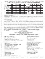
Purchaser's Signature _________________________ Date __________ Dealer's Signature ________________________ Date __________

PRE-DELIVERY SERVICE

CHECK AND ADJUST OR LUBRICATE AS REQUIRED

See Operator’s Manual for Details

Inspection Performed - Warranty and Safety Procedures Explained - Installation Complete

  I have informed the Purchaser of this product of Warranty terms, provisions, and procedures that are applicable, reviewed the contents of the Operator’s Manual

including safety equipment, safe operation, and maintenance, reviewed the Safety Signs on implement (and tractor if possible), and  Purchaser’s responsibility to

train his operators in safe operation.

  IMPLEMENTS

: I have explained that Deflectors, Chain Guards, or Solid Skirts must be maintained in good repair and installed except in areas where persons,

vehicles, livestock, or other property will not be endangered by thrown objects and where such safety equipment would prevent the mower’s reasonable performance

of its assigned task.

  DRIVELINES: 

 I have made certain that all driveline, gearbox, and other shields are in good repair and fastened securely in place to prevent injuries  from

entanglement or thrown objects.


HYDRAULIC MACHINES:

  I have explained the necessity of using clean hydraulic oil, changing filters as instructed, stopping leaks, damage caused by

operating with over-heated oil, caring for hoses, using hoses of proper rating, the necessity of maintaining the specified operating pressure, and the potential hazard

of oil's penetrating the skin.


 BOOM-TYPE or FOLDING-TYPE IMPLEMENTS:

  I have explained that it is not possible to guard against thrown objects when the head is lifted off ground

and that operator is responsible to watch out for persons in the area.  I have explained that the lifted mower head or boom can contact overhead obstructions with

damage to cables and telephone lines and possible injury.  I have explained that the extended head or boom or retracted boom can contact power lines with resulting

electrocution injury or death and that operator is responsible for keeping clear of such hazards.

Dealer’s Signature ___________________________________ Date ______________

I have been instructed on the  paragraphs above, received and have been instructed in the contents of the Operator’s Manual including safety signs, safety
equipment, safe operation, maintenance, and the potential hazards of unauthorized alteration or modification of the product.  I have been informed of the warranty
provisions and know that the warranty is not in effect until this form is received by Alamo Group.
I understand the Implement Guarding statements above and the potential hazards of operating without such guards. I understand that the operator is responsible for
the safety of others in the area. I have examined the product and accept it as being complete and in satisfactory condition with all required guards.

Purchaser’s Signature ___________________________________ Date ______________

Alamo Ind. Model

Serial No.

Purchase Date

M.I.

First Name

Purchaser

Last Name
Street & No., RFD,

Box, &/or Apt. No.

State or

Province

State or

Province

ZIP

ZIP

City

City

Dealer

MONTH

DAY

YEAR

ALAMO INDUSTRIAL

®

 WARRANTY REGISTRATION INFORMATION

 TEAR • TEAR • TEAR • TEAR • TEAR • TEAR • TEAR • TEAR • TEAR • TEAR • TEAR • TEAR • TEAR • TEAR • TEAR • TEAR • TEAR • TEAR • 

TEAR • TEAR • TEAR • TEAR • TEAR • TEAR • TEAR

LUBRICATION  & HYDRAULICS

†

Gearbox Speed Increaser (Oil Levels)

†

Hydraulic Oil Level (External. Tank)

†

Tractor Hydraulic Oil Level

†

Hydraulic Hoses (Not Kinked Tighten Connections)

†

Front Pump Drive (Assembly Is Tight And Shaft Properly Aligned)

MOWER

†

Spindle And Motor Bolts Properly Torqued

†

Spindle Oil Level

†

Blade Carrier Bolts Properly Torqued / Retaining Pin In Place

†

Mower Cutting Height And Level Adjusted

†

Belt Alignment And Tension Adjusted

†

Cutting Shaft Bearings Lubricated

†

All Hardware Properly Torqued

†

Tire And Air Pressure / Lug Nuts (Correct Torque)

†

Wheel Bearings (Check, Grease, And Preload)

ATTACHMENTS & INSTALLATION

†

Deflectors Front And Rear

†

Shredding Attachments

†

Correct Blade Rotation Direction

†

Axle Arms And Beams

†

Tongue And Control Rods (Installed And Adjusted)

†

All Bolts - Pins And Nuts (Proper Torque)

MOWER TO TRACTOR CONNECTION

†

Draw Bar Length (Check And Set)

†

A-Frame Pivot & Links

†

Control Rods (Adjusted Equal)

†

Axle Height (Adjusted)

†

Cutting Height (Adjust)

†

Mount Kit Pre-Operation Check Complete

†

Mower Wing (Adjust Level With The Center)

†

Mower Wing (Check For Proper Raising Operation)

†

C.V. Drivelines (Check Max Turn Radius)

†

Pull Type Hitch (Height Adjustment)

†

Mounting Hardware Properly Torqued

SAFETY ITEMS

†

Protective Shields (Operation And Installation)

†

Driveline Clutch (Torque Limiter) (Adjust And Run In)

†

Safety Decals (Installed)

†

Operator’s Manual (Supplied)

†

Tractor PTO Shield (Installed)

†

S.M.V. Emblem (Installed If Needed)

†

Neutral Safety & Cut - Off Switches

†

Safety Tow Chain (Installed)

1.  PRINT FIRMLY.     2.  REMOVE WHITE COPY FOR CUSTOMER RECORDS.     3.  REMOVE YELLOW COPY FOR DEALERS RECORDS.     4.  MAIL LAST CARD POSTAGE FREE.

CUSTOMER COPY

Summary of Contents for HYDRO 88

Page 1: ...tential hazards of unauthorized alteration or modification of the product I have been informed of the warranty provisions and know that the warranty is not in effect until this form is received by Alamo Group I understand the Implement Guarding statements above and the potential hazards of operating without such guards I understand that the operator is responsible for the safety of others in the a...

Page 2: ......

Page 3: ...otential hazards of unauthorized alteration or modification of the product I have been informed of the warranty provisions and know that the warranty is not in effect until this form is received by Alamo Group I understand the Implement Guarding statements above and the potential hazards of operating without such guards I understand that the operator is responsible for the safety of others in the ...

Page 4: ......

Page 5: ...ion maintenance and the potential hazards of unauthorized alteration or modification of the product I have been informed of the warranty provisions and know that the warranty is not in effect until this form is received by Alamo Group I understand the Implement Guarding statements above and the potential hazards of operating without such guards I understand that the operator is responsible for the...

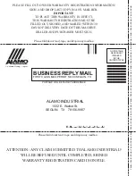
Page 6: ...S PLEASE FILL OUT OWNER WARRANTY REGISTRATION INFORMATION SIGN AND DROP LAST COPY IN ANY MAILBOX IMPORTANT TO PLACE THIS WARRANTY IN EFFECT THIS WARRANTY REGISTRATION MUST BE FILLED OUT SIGNED AND MAILED WITHIN 30 DAYS OF DELIVERY DATE OF THIS MACHINE DEALER AND PURCHASER MUST SIGN ATTENTION ANYCLAIM SUBMITTEDTOALAMO INDUSTRIAL WILL BE REFUSED UNTIL COMPLETED SIGNED WARRANTYREGISTRATION CARD IS ON...

Page 7: ...ALAMO INDUSTRIAL 1502 E Walnut Seguin Texas 78155 830 379 1480 OPERATOR S MANUAL with PARTS LISTING HYDRO 88 96 Published 08 04 Part No 803342 2004Alamo Group Inc ...

Page 8: ...ipment properly attached to minimize the chance of accidents BEFORE YOU START Read the safety messages on the implement and shown in your manual Observe the rules of safety and common sense WARRANTY INFORMATION Read and understand the complete Warranty Statement found in this Manual Fill out the Warranty Registration Form in full and return it to Alamo within 30 Days Make certain the Serial Number...

Page 9: ...RATION SECTION 4 1 MAINTENANCESECTION 5 1 Lubrication Information 5 2 Hydraulic Oil Filters and Components 5 3 Drive Belts 5 4 Cutting Height 5 4 Roller Bearing Replacement 5 5 Cuttershaft Bearing Replacement 5 6 Changing Rotation Forward or Reverse 5 8 Cutter Knives Replacement 5 8 Hydraulic Motor Disassembly 5 9 Trouble Shooting 5 11 Hydraulic Filter 5 12 Storage 5 15 Torque Settings 5 15 PARTS ...

Page 10: ......

Page 11: ...Safety Section 1 1 HYDRO 88 96 04 02 2003 Alamo Group Inc SAFETY SECTION ...

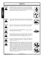
Page 12: ...mplement This equipment should only be operated by those persons who have read the Manual who are responsible and trained and who know how to do so safely and responsibly The Safety Alert Symbol combined with a Signal Word as seen below is used throughout this manual and on decals which are attached to the equipment The Safety Alert Symbol means ATTENTION BECOME ALERT YOUR SAFETY IS INVOLVED The S...

Page 13: ...clearly visible and legible When transporting the Equipment use the Tractor flashing warning lights and follow all local traffic regulations SG 6 WARNING Operate this Equipment only with a Tractor equipped with an ap proved roll over protective system ROPS Always wear seat belts Serious injury or even death could result from falling off the tractor particularly during a turnover when the operator ...

Page 14: ... securely supported or blocked up to prevent sudden or inadvertent falling which could cause serious injury or even death SG 14 DANGER Do not operate this Equipment with hydraulic oil leaking Oil is expensive and its presence could present a hazard Do not check for leaks with your hand Use a piece of heavy paper or cardboard High pressure oil streams from breaks in the line could penetrate the ski...

Page 15: ... operating conditions Do not operate the Tractor with weak or faulty brakes When operating down a hill or on wet or rain slick roads the braking distance increases use extreme care and reduce your speed When operating in traffic always use the Tractor s flashing warning lights and reduce your speed Be aware of traffic around you andwatch out for the other guy SG 19 Test the equipment at a slow spe...

Page 16: ... Implement Children can slip or fall off the Equipment and be injured or killed Children can cause the Implement to shift or fall crushing themselves or others SG 25 WARNING Do not exceed the rated PTO speed for the Implement Excessive PTO speeds can cause Implement driveline or blade failures resulting in serious injury or death SG 26 DANGER NEVER use drugs or alcohol immediately before or while ...

Page 17: ...sed stand to access high spots which cannot be reached from gound level Slipping and falling can cause serious injury or death SG 33 WARNING Avoid contact with hot surfaces including hydraulic oil tanks pumps motors valves and hose connections Relieve hydraulic pressure before performing maintenance or repairs Use gloves and eye protection when servicing hot components Contact with a hot surface o...

Page 18: ...g parts of this machine have been designed and tested for rugged use However the blades could fail upon impact with heavy solid objects such as metal guard rails and concrete structures Such impact could cause the broken objects to be thrown outward at very high velocities To reduce the possibility of property damage serious injury or even death never allow the cutting blades to contact such obsta...

Page 19: ...nd collected debris from the mower deck SGM 12 WARNING WARNING DO NOT weld or repair rotating mower components Welds and other repairs may cause severe vibration and or component failure resulting in parts being thrown from the mower causing serious bodily injury See your Authorized Dealer for proper repairs SGM 13 DANGER The Mower is designed for certain mowing applications and is rated to cut up...

Page 20: ...oken components Missing broken or worn items must be replaced at once to reduce the possibility of injury or death from thrown objects entanglement or blade contact SFL 5 DANGER Do not put hands or feet under mower decks Blade Contact can result in serious injury or even death Stay away until all motion has stopped and the decks are securely blocked up SFL 2 DANGER There are obvious and hidden pot...

Page 21: ...requiredto mow reduce wear and tear on the Mower drivetrain spread cut material better eliminate streaking and make the final cut more uniform SFL 6 STOP MOWING IF PASSERSBY ARE WITHIN 100 YARDS UNLESS DANGER Make sure the PTO shield integral driveline shields and input shields are is installed when using PTO driven equipment Always replace any shield if it is damaged or missing S3PT 8 WARNING Nev...

Page 22: ...se the Implement and Tractor to pivot violently resulting in loss of steering control serious injury or even death Never allow the Implement to contact obstacles S3PT 12 DANGER Always disconnect the main PTO Driveline from the Tractor before performing service on the Implement Never work on the Implement with the tractor PTO driveline connected and running Rotating Parts Blades or Drivelines could...

Page 23: ...ission Tractorbrakingdistances can be substantially increased by the momentum of the rotating Mower bladesdrivingtheTractortransmissioneventhoughtheTractorclutchhas beendisengaged InstallanoverrunningclutchbetweentheTractorPTO and the Mower driveline to prevent this potentially dangerous situation S3PT 16 WARNING When attaching the Implement input driveline to the Tractor PTO it is important that ...

Page 24: ...Safety Section 1 14 SAFETY HYDRO 88 96 04 02 2003 Alamo Group Inc SAFETY HYDRO 88 96 FLAIL DECALS 7 13A 18 19 18 19 20 25 23 24 21 26 ...

Page 25: ... INSTRUC Cutting Height Adjustment 11 002457 1 INSTRUC Lubrication Chart 12 02966305 1 INSTRUC Use Universal Hydraulic Oil 13 03200432 1 INSTRUC Genuine Parts Flail 13A 00763977 1 INSTRUC Notice to Owners 14 001650 1 LOGO Alamo Group by Mott 7 26 x 7 5 15 02960766 1 LOGO Alamo Group 4 x 5 16 001651 1 LOGO Alamo Group by Mott 4 1 2 x 16 1 2 17 nfs 1 PLATE Alamo by Mott 18 1458392 2 REFLECT Red Refl...

Page 26: ...fety Section 1 16 SAFETY HYDRO 88 96 04 03 2003 Alamo Group Inc SAFETY 8 000108 OPERATINGINSTRUCTIONS 2 00725739 USE REPAIR SHIELDS GUARDS 13 03200432 GENUINE PARTS 12 02966305 USE UNIVERSAL HY DRAULICOIL ...

Page 27: ...INCH POINTS 4 02967668 Thrown objects 3 00756059 DECAL LEAK DETECTION 6 02971123 WARNING PRESS TANK GREASE FITTING INSIDE 9 000678 INSTRUCTION 7 03200347 SMV SYMBOL 10 002023 CUTHEIGHTINSTRUCTION 13A 00763977NOTICETOOWNERS 17 nfs SERIAL PLATE 18 RedReflector 19 YellowRefelctor R7 24 97 ...

Page 28: ...Safety Section 1 18 SAFETY HYDRO 88 96 03 94 2003 Alamo Group Inc SAFETY 11 002457 LUBRICATIONCHART 1 002369 MULTI HAZARD DANGER ...

Page 29: ...Safety Section 1 19 SAFETY HYDRO 88 96 04 03 2003 Alamo Group Inc SAFETY 20 02977417 LUBRICATIONCHART 15 02960766 Alamo Industrial Logo 14 001650 Alamo Industrial Logo 16 001651 Alamo Industrial Logo ...

Page 30: ...f all equipment with which the employee is or will be involved Employer Responsibilities To ensure employee safety during Tractor and Implement operation it is the employer s responsibility to 1 Train the employee in the proper and safe operation of the Tractor and Implement 2 Require that the employee read and fully understand the Tractor and Implement Operator s manual 3 Permit only qualified an...

Page 31: ...Introduction Section 2 1 HYDRO 88 96 03 94 2003 Alamo Group Inc INTRODUCTION SECTION ...

Page 32: ...r operator how to work the Mower correctly and attend to appropriate maintenance The Trouble Shooting Guide helps diagnose difficulties with mower and offers solution to the problems Safety is of primary importance to the owner operator and to the manufacturer The first section of this manual includes a list of Safety Messages that if followed will help protect the operator and bystanders from inj...

Page 33: ... strongly recommends the use of Chain Gaurds Deflectors or Solid Skirts for Agricultural purposes as well to reduce the risk of property damage serious bodily injury or even death from objects thrown out by or from contact with the Cutting Blades At least 20 of the tractor s total weight must be on the front tires with the Mower lifted to provide adequate traction for safe steering under good cond...

Page 34: ...d Mower 2 Fill out the Warranty Card in full Be sure to answer all questions including the Serial Number of the Mower Mail within 30 days of delivery date of this implement NOTE Warranties are honored only if completed Owner Registration and Warranty forms are received by Alamo Group within thirty days of delivery of the mower 3 Record the Mower Model and Serial Numbers on the Warranty page at the...

Page 35: ...Assembly Section 3 1 HYDRO 88 96 03 94 2003 Alamo Group Inc ASSEMBLY SECTION ...

Page 36: ...boxandlaypartsouttomakelocation easy Refer to the parts lists and exploded view drawings for more detail This mower is shipeed partially assembled Assembly will be easier if components are aligned and loosely assembled before tightening hardware CAUTION Always use personal protection devices such as eye ear and foot protectors during assembly HOSE ATTACHMENT Attach the Pressure Hose 1 to the Hydra...

Page 37: ...e the following procedure 1 Attach the Speed Increaser Mount Plate to the tractor loosely Refer to the installation drawing supplied in the packing box for specific instructions 2 Grease the tractor PTO shaft and slide the Speed Increaser on Install the 1 2 bolts and bushings between the Speed Increaser and Mount Plate Do not tighten bolts at this time 3 With the tractor in idle and the PTO engage...

Page 38: ......

Page 39: ...OPERATION SECTION Operation Section 4 1 2002 Alamo Group Inc ...

Page 40: ...designed to familiarize instruct and educate safe and proper mower use to the operator Pictures contained in this section are intended to be used as a visual aid to assist in explaining the operation of a Hydro flail mower and are not specific to any model Some pictures may show shields removed for picture clarity NEVER operate implement without all shields in place and in good operational conditi...

Page 41: ...o lea para que le traduzca las medias de seguridad SG 3 PELIGRO LEA EL INSTRUCTIVO 7 PUMPAND SPEED INCREASERATTACHMENT 4 12 8 PRE OPERATION INSPECTIONAND SERVICE 4 13 8 1 Tractor Pre Operation Inspection Service 4 13 8 2 Mower Pre Operation Inspection Service 4 14 9 DRIVING THE TRACTORAND MOWER 4 17 9 1 Starting the Tractor 4 18 9 2 Raising The Mower 4 18 9 3 Brake and Differential Lock Setting 4 ...

Page 42: ...se Unit Specifications 88 and 96 Cutting Widths Hydraulic Power Sealed Hydraulic System Hydraulic Overload Protection Flail Cutting Action Cutter Shaft Balanced 4 1 2 Drawn Steel Tubing Full Span Roller 0 6 Cutting Height 10 Gauge Flail Deck with 5 16 End Plates Coarse Cut Flail Knives 40 HP Tractor Front Rear Deflectors ...

Page 43: ...ator s ability to operate the Equipment safely Before operating the Tractor or Implement an operator on prescription or over the counter medication must consult a medical professional regarding any side effects of the medication that would hinder their ability to operate the Equipment safely NEVER knowingly allow anyone to operate this Equipment when their alertness or coordination is impaired Ser...

Page 44: ...fety Devices If transporting or operating the tractor and mower near a public roadway the tractor must be equipped with proper warning lighting and a Slow Moving Vehicle SMV emblem which are clearly visible from the rear of the unit Lights and a SMV emblem must be equipped directly on implements if the visibility of the tractor warning signals are obscured Maintain all manufacturer equipped safety...

Page 45: ...er diameter hitch pins CAT I Implement Hitch Specification Width from outside to outside A frame 26 7 8 Quick Hitch width inside lug to lug 27 1 8 Height from bottom hitch pin to top pin 18 Lower pin diameter 7 8 Upper pin diameter 3 4 Linch pin diameter 15 32 CAT II Implement Hitch Specification Width from outside to outside A frame 32 3 8 Quick Hitch width inside lug to lug 33 5 8 Height from bo...

Page 46: ...e seat until the tractor its engine and all moving parts have come to a complete stop WARNING Do not mount the Tractor while the tractor is moving Mount the Tractor only when the Tractor and all moving parts are completely stopped SG 12 Before getting onto the tractor the operator must read and completely understand the mower and tractor operator manuals If any part of either manual is not complet...

Page 47: ...Locate the engine throttle control Locate the brake pedals and the clutch Locate the parking brake Locate the PTO control Locate the 3 point hitch control lever Locate the hydraulic control lever Locate the light control switch DANGER Start the Tractor only when properly seated in the Tractor seat Starting a Tractor in gear can result in injury or death Read the Tractor operator s manual for prope...

Page 48: ...set of mowerA frame lift lugs Note Set the 3 point lift control to Position Control so that the lift arms maintain a constant height when attaching the mower See the tractor Operator s Manual for correct settings when attaching 3 point equipment 4 Turn off the tractor engine and dismount 5 One lift arm at a time align arm end hole between the set of lower rear hitchplates Insert hitch pin through ...

Page 49: ...d 2 Shut down the tractor place the transmission in park and set the parking brake before dismounting 3 One section at a time place lifting device scissors jack or hydraulic jack under center of cutter housing 4 Remove hex nuts washers and carriage bolts from bracket at each end of roller Make certain that roller bracket is free to move once the fasteners are removed Astuck roller could drop unexp...

Page 50: ...jects thrown from the Blades SRM 7 To attach the Speed Increaser and Pump to the tractor use the following procedure 1 Attach the Speed Increaser Mount Plate to the tractor loosely Refer to the installation drawing supplied in the packing box for specific instructions 2 Grease the tractor PTO shaft and slide the Speed Increaser on Install the 1 2 bolts and bushings between the Speed Increaser and ...

Page 51: ...g or loose fittings Make sure all pins have cotter pins and washers Serious injury may occur from not maintaining this Implement in good working order SG 21 DANGER DO NOT allow any person under a folded wing unless wing is securely locked up or supported DO NOT approach the Implement unless the Tractor is turned off and all motion has ceased Never work under the frame work or any lifted component ...

Page 52: ...king condition Damaged and or broken parts should be repaired and or replaced immediately To ensure the mower is ready for operation conduct the following DANGER Replace bent or broken blades with new blades NEVER ATTEMPT TO STRAIGHTEN OR WELDONBLADESSINCETHISWILLLIKELYCRACKOROTHERWISEDAMAGETHEBLADE WITH SUBSEQUENT FAILURE AND POSSIBLE SERIOUS INJURY FROM THROWN BLADES SGM 10 DANGER All Safety Shi...

Page 53: ...ove of the PTO shaft Inspect that the 3 point hitch pins are the proper size correctly installed and secured to the tractor lift arms with retaining pins inserted Ensure that a properly rated safety tow chain is equipped securing the mower to the tractor DANGER All Safety Shields Guards and Safety devices including but not limited to the Deflectors Steel Guards Gearbox Shields PTO integral shields...

Page 54: ...nd excessive wear Make sure the mower is securely blocked up before crawling beneath Replace damaged worn and missing knives as complete sets to maintain cuttershaft balance Remove any grass or other debris which may be wrapped around the cuttershafts Inspect the condition of deck skid shoes and hardware Check the overall condition of the mower main frame DANGER Do not operate this Equipment with ...

Page 55: ...stance increases use extreme care and reduce your speed in these conditions When operating in traffic always use the Tractor s flashing warning lights and reduce your speed Be aware of traffic around you and watch out for the other guy SG 19 WARNING DANGER This Implement is wider than the Tractor Be careful when operating or transporting this equipment to prevent the Implement from running into or...

Page 56: ...CTIVE BRAKINGACTION 9 2 Raising the Mower Using the tractor 3 point hitch control lever raise the mower off the ground about 6 or just high enough to clear any ground obstacles When raising the mower make sure all connection points are securely attached and at least 1 clearance is maintained between the driveline and the deck If necessary place an upper lift stop on the 3 point hitch control lever...

Page 57: ...hen turning especially when the wings are lowered Always disengage the tractor differential lock when turning When engaged the differential lock will prevent or limit the tractor from turning During normal cutting conditions locking the differential provides no benefit and should not be used Be aware of the operating conditions Do not operate the Tractor with weak or faulty brakes When operating d...

Page 58: ...tain sufficient deck to ground clearance Blade contact with the ground may cause soil rocks and other debris to be thrown out from under the mower resulting in possible injury and or property damage Ground contact also produces a severe shock load on the mower drive and to the mower blades resulting in possible damage and premature wear WARNING Mow at the speed that you can safely operate and cont...

Page 59: ... person on the street Engage the PTO shaft at low engine RPM and speed the engine up after blades are fully engaged Never engage the PTO shaft at a high engine RPM This could cause damage to the PTO shaft as well as the Speed Increaser and Pump Always operate PTO at the recommended RPM when mowing This is necessary to maintain proper blade speed and to produce a clean cut Propergroundspeedforcutti...

Page 60: ...nce Immediately idle the engine speed and disengage the PTO Wait for all mower motion to stop then raise the mower and move the tractor and mower off the object Inspect the area and remove or mark the location of the debris Inspect the condition of the mower and make any needed repairs immediately Make sure the blades are not damaged and the cuttershafts are balanced before resuming operation Many...

Page 61: ...gage the PTO again until all bystanders are well past the 100 yard distance Front and Rear Deflectors Chain Guards or Bands are installed and in good workable condition Mower section is running close to and parallel to the ground without exposed Blades Passersby are outside the existing thrown object zone All areas have been thoroughly inspected and all foreign material such as rocks cans glass an...

Page 62: ...ially serious hazard and could cause serious injury or even death from objects thrown from the Blades SRM 7 Ground speed is achieved by transmission gear selection and not by the engine operating speed The operator may be required to experiment with several gear range combinations to determine the best gear and range which provides the most ideal performance from the mower and most efficient tract...

Page 63: ...ngs or debris to collect near drivelines slip clutches and gearboxes Periodically shut down the Tractor and Mower and clean clippings and collected debris from the mower deck SGM 12 WARNING Only operate the mower from the tractor operator s seat with the seatbelt securely fastened on a ROPS or cab equipped tractor The mower is designed for cutting grass and small weeds Sharp blades will produce a ...

Page 64: ... on the top link hitch pin When the pin is loose and easy to rotate remove the pin from the mower Next remove both lower hitch pins 10 6 Shutting Down the Mower To shut down the mower first bring the tractor to a complete stop Then slow down the mower by reducing the engine speed before disengaging the PTO Wait for all rotating motion to stop before proceeding to drive or shut down the tractor Par...

Page 65: ...d in the raised position select a level area and block the mower up securely before attempting to disconnect it from the tractor After disconnecting the 3 lift points remove the speed increaser from the tractor PTO shaft Lay the speed increaser and pump down carefully to avoid damaging the speed increaser and pump Do not let the speed increaser fall into mud or dirt which can contaminate the beari...

Page 66: ...ers of operating the tractor and mower and the possibility of accidents are not left behind when you finish mowing an area Therefore the operator must use good judgement and safe operation practices when transporting the tractor and mower between locations By using good judgement and following safe transport procedures the possibility of accidents while moving between locations can be substantiall...

Page 67: ...ER Never allow children or other persons to ride on the Tractor or Implement Falling off can result in serious injury or death SG 10 The SMV Slow Moving Vehicle emblem is universal symbol used to alert drivers of the presence of equipment traveling on roadways at a slow speed SMV signs are a triangular bright orange with reflective red trim for both easy day and night visibility Make sure the SMV ...

Page 68: ...or dealer for lighting kits and modifications available to upgrade the lighting on older tractor models When operating on public roads have consideration for other road users Pull to the side of the road occasionally to allow following traffic to pass Do not exceed the legal speed limit set in your area for agricultural tractors Always stay alert when transporting the tractor and mower on public r...

Page 69: ...e front and rear of the tractor utilizing the proper tie down locations as specified by the tractor manufacturer Arrange the chains so that when tightened the chains are pulling downward and against themselves Carefully tighten the securing chains or other fasteners used as much as possible using boomers or binders to apply maximum tension Use extreme care when attaching and removing the securing ...

Page 70: ... belts D ReplaceOn OffSwitch A Adjust safety switch B Trace electrical circuit for short A Readjust belt tension and check idler springs B Free the shaft C Adjustreliefvalve D Replaceorrebuild A Fill to proper level B Adjustreliefvalve C Removeobstruction extra items which are not standard A Add hydraulic fluid B Cleanorreplacebreather valve C Replacefilter D Replaceorrebuild A Adjustreliefvalve S...

Page 71: ...ts replaceallwornparts and flush hydraulic system 7 System noisy 8 Sluggish response to accelerationordeceleration 9 Motor turns while unloaded but slows down or stops when load is applied 10 Motor will not turn A Air in system due to low oil level B Loose suction line C Clogged suction filter D Internal pump or motor damage A Air in system B Internal pump or motor wear or damage A Scored back pla...

Page 72: ......

Page 73: ...Operation Section 4 1 HYDRO 88 96 03 94 2003 Alamo Group Inc MAINTENANCE SECTION ...

Page 74: ...The accompanying illustration shows lubrication points The chart gives the frequency of lubrication in hours based on normal operating conditions Severe or unusual conditions may require more frequent lubrication LUBRICATION The HYDRO88 must be serviced daily to achieve the best operation and longest life Good quality grease from a hand grease gun in all grease fittings should be sufficient FIGURE...

Page 75: ...hich is used to fill the reservoir with oil To help prevent dirt from entering the tank clean the top of the reservoir before removing the cap THE BREATHER CAP HOLDS APPROX 11 PSI PRESSURE IN TANK REMOVE FILLER CAP ONLY AFTER RELIEVING PRESSURE IN THE TANK BY USING THE PRESSURE RELIEF LOCATED UNDER THE BREATHER ELEMENT Stand off to one side when removing the breather cap element to prevent possibl...

Page 76: ... arm spring and belt guard ADJUSTING CUTTING HEIGHT Figure 3 1 Lower cutter unit to ground and place control valve levers in FLOAT position 2 Place lifting device scissors jack hydraulic jack under center of cutter housing 3 Remove hex nuts washers and carriage bolts from bracket at each end of roller Make certain that roller bracket is free to move once the fasteners are removed A stuck roller co...

Page 77: ... If replacing with new roller bearing and housing assemblies proceed to step 8 4 Remove grease fitting from the top of bearing housing 5 Remove bearing from housing By rotating Bearing 90O sideways and line up with notches in Bearing Housing then pull out 6 Installnewbearingintohousing Bearingmustbeinstalledwithgreaseholeinbearingalignedwithgreasefitting hole in housing 7 Reinstall grease fitting ...

Page 78: ... to cutterhousing then remove bearing and housing assembly NOTE There are two tapped holes in the housing which can be used to pull bearing and housing assembly out by using special tool No 701627 6 Using a jack to align parts install bearing and housing assembly to cutter unit and make certain that bearing setscrew is located in keyway on cuttershaft Grease bearing and install cap over fitting If...

Page 79: ...all key and pulley Secure with cuttershaft fasteners 13 Remove jack and check shaft rotation Reinstall knives which were removed 14 Reinstall drive belts then secure motor mounting bracket to cutterhousing 15 Reinstall idler arm spring 16 Reinstall belt guard 17 Remove supports lower unit to ground and test unit Reinstall outboard fender if not already installed CUTTERSHAFT REPLACEMENT NOTE Itisre...

Page 80: ...eg counter clockwise looking from the mainfold block end of the motor This changes the present inlet port into the outlet port of the motor Re install manifold block in the same orientation as it was removed Install case drain hose The Motor Mount Plate has 4 holes located at approximately 4 10 11 and 5 o clock positions as viewed from rear of Motor The 2 unused mounting holes will now be used to ...

Page 81: ... be needed to disassemble the piston block 2 ea 3 8 I D x 1 1 8 O D flat washer 1 ea 3 8 I D x 3 1 4 N C capscrew 1 ea 3 8 N C nut Place one of the flat washers over the 3 8 x 3 1 4 capscrew and place this through the center of the piston block Place the other washer over the capscrew and let it rest on te three pins Screw the nut on and compress the spring inside the piston block Use a pair of sn...

Page 82: ... bearing and second thrust washer on drive shaft Install second snap ring in front groove on drive shaft 3 Replace needle bearing in housing if necessary Install shaft in housing assembly and install washer Oil O D of new shaft seal and press into position Retain with snap ring 4 Compress pin keeper and install in the spline area of the piston block 5 Install the three pins in the special grooves ...

Page 83: ...engine on a closed loop system or returning the control valve spool to neutral on an open center system themotorwillfree wheelafter ithasleakedoff Thisisinher entinthedesign Onaclosed looporpropulsionsystem the motor will not free wheel as long as charge pressure is maintained to and from the motor A Disassemble motor in spect parts and replace as necessary Case drain flow should not exceed 1 5 GP...

Page 84: ...CE CHANGING HYDRAULIC SYSTEM FILTER A large capacity filter is located on top of the hydraulic oil reservoir Figure 8 The filter will trap particles which are 001 inch or larger The filter needs to be changed after the first 10 hours of operation and every 200 hours thereafter FIGURE 8 ...

Page 85: ...n removing the Breather Cap Element and while venting the excess air to prevent possible injury Depress the spring loaded Pressure Valve to release any excess air Replace Breather Cap Element 3 Loosen the four bolts on the filter cover Figure 9 Remove one bolt from the filter to aid in removing the filter cover Figure10 4 Push the filter cover down and slowly twist the filter cover off Figure 11 5...

Page 86: ...RAULIC SYSTEM FILTER cont d 6 Remove filter Inspect material trapped by the filter It can indicate parts wear in the system Figure 13 7 Install the new filter 8 Reinstall filter spring and filter cover Replace the one bolt which had previously been removed Tighten all bolts in an even manner FIGURE 13 ...

Page 87: ...Make replacements immediately 5 Store the mower in a clean dry place with the mower head resting on blocks 6 Use spray touch up enamel where necessary to prevent rust and maintain the appearance of the mower PROPER TORQUE FOR FASTENERS The chart lists the correct tightening torque for fasteners When bolts are to be tightened or replaced refer to this chart to determine the grade of bolts and the p...

Page 88: ......

Page 89: ...HYDRO 88 96 03 94 2003 Alamo Group Inc PARTS SECTION ...

Page 90: ...e name and address of the person or organization ordering the parts who should be charged and if possible the serial number of the machine for which the parts are ordered 3 The Purchase Order must clearly list the quantity of each part the complete and correct part number and the basic name of the part 4 The Manufacturer reserves the right to substitute parts where applicable 5 Some parts are unli...

Page 91: ...HYD MOTOR REPLACEMENT PARTS P N 001602 16 HYD SCHEMATIC 14 MOWER ASY 88 22 MOWER ASY 96 18 PUMP ASY 12 PUMP CONNECTION 13 SPEED INCREASER PUMP ASY 7 SPEED INCREASER P N 00768956 NEW STYLE 10 SPEED INCREASER P N 02897900 OLD STYLE 8 HYDRO 88 96 08 04 2004 Alamo Group Inc Parts Section 3 ...

Page 92: ...GENERAL ASY HYDRO 88 96 08 04 2004 Alamo Group Inc Parts Section 4 ...

Page 93: ...15 00059000 2 BOLT 16 107032 2 SPACER 17 103715 2 A FRAME 18 02776600 3 BOLT 19 100743 2 HITCH PIN 20 2196 2 CLIP LYNCH PIN 21 102667 1 SPACER 22 02959332 1 BOLT 23 00037200 2 LOCKNUT 24 107031 2 BRACE 25 00751530 1 FILTER ELEMENT BREATHER 27 02961001 1 FILTER ELEMENT 28 02049700 1 SIGHT GAUGE 29 101779 1 PIN 30 103717 1 SPACER 31 103716 2 SPACER 32 02972678 1 SPRING FILTER CARTRIDGE 33 02973782 1...

Page 94: ...LTER ASY W ELEMENT 1 02961001 1 FILTER ELEMENT ONLY 2 02972678 1 SPRING FILTER CARTRIDGE 3 02973782 1 VALVE FILTER BYPASS 4 02978349 1 FILTER COVER 5 02978354 1 SEAL KIT 6 02978355 1 NUT BOLT KIT F FILTER COVER HYDRO 88 96 08 04 2004 Alamo Group Inc Parts Section 6 ...

Page 95: ...ION 1 02897900 1 SPEED INCREASER OLD STYLE STEEL HOUSING 00768956 SPEED INCREASER NEW STYLE ALUMINUM HOUSING 2 00019600 2 LOCKWASHER 3 00750959 2 BOLT 4 002460 1 PUMP 5 02961098 1 ADAPTER HYD ELBOW HYDRO 88 96 08 04 2004 Alamo Group Inc Parts Section 7 ...

Page 96: ...SPEED INCREASER P N 02897900 OLD STYLE HYDRO 88 96 08 04 2004 Alamo Group Inc Parts Section 8 ...

Page 97: ...0751951 1 BEARING CUP 14 00751533 1 BEARING CONE 15 00749201 3 BEARING CUP 16 00749200 3 BEARING CONE 17 00751953 1 SPACER RING 18 00751955 1 HOUSING 19 00751956 1 HOUSING 20 00751957 2 DOWEL PIN 21 00751958 1 GASKET 015 22 00751971 2 SPACER RING 24 00751959 AR SHIM 005 ALUM 25 00751960 AR SHIM 007 ALUM 26 00751961 AR SHIM 020 ALUM 28 00751963 4 SHIM 005 ALUM 29 00751964 1 SHIM 005 FIBRE 30 007519...

Page 98: ...SPEED INCREASER P N 00768956 NEW STYLE HYDRO 88 96 08 04 2004 Alamo Group Inc Parts Section 10 ...

Page 99: ... PIN 13 00754531 1 HOUSING 14 00754532 1 GASKET 15 00754533 1 FLANGE 16 00754534 1 GASKET 17 00754535 1 DIPSTICK 18 00754536 5 ALUMINUM WASHER 19 00754537 4 PLUG 20 00754538 2 DOUBLE LIP SEAL 21 00754539 1 BEARING 22 00754540 1 RETAINING RING 23 00754541 3 BEARING 24 00754542 1 SHAFT 25 00754543 2 KEY 26 00754544 1 GEAR 540 RPM 00756532 1 GEAR 1000 RPM 27 00754545 1 PINION GEAR 540 RPM 00756531 1 ...

Page 100: ...LATE ASY 3 03200408 1 CAMPLATE INSERT 4 03200404 1 SPLINED SHAFT 5 001644 2 BEARING CONE KIT 6 03200409 1 O RING 7 027664400 6 BOLT 8 03200411 1 WASHER 9 03200412 1 RETAINING RING 10 03200413 2 RETAINING RING 11 03200414 1 SHAFT SEAL HYDRO 88 96 08 04 2004 Alamo Group Inc Parts Section 12 ...

Page 101: ...CTION ITEM PART NO QTY DESCRIPTION 1 002460 1 PUMP ASY W FITTINGS 2 03200283 1 STRAIGHT ADAPTER 3 02957622 1 STRAIGHT ADAPTER 4 02961098 1 ADAPTER HYD ELBOW HYDRO 88 96 08 04 2004 Alamo Group Inc Parts Section 13 ...

Page 102: ...1 SUCTION HOSE 3 107558 1 HOSE 4 02742800 1 HOSE 5 107557 1 HOSE 6 02275900 1 HOSE 7 02960409 1 ADAPTER TUBE ELBOW 8 03200277 1 HOSE 9 02956851 1 ADAPTER HYD ELBOW 10 002529 1 STRAIGHT ADAPTER REDUCER 11 0320350 1 FILLER PLUG HYDRO 88 96 08 04 2004 Alamo Group Inc Parts Section 14 ...

Page 103: ... 106458 1 MOTOR MOUNT PLATE 6 001654 1 ADAPTER ELBOW 7 00748823 2 BOLT 8 00001800 2 LOCKNUT 9 001602 1 MOTOR 10 02090900 2 ADAPTER ELBOW 11 03200283 1 STRAIGHT ADAPTER 12 001574 1 CAP NUT 13 63092200 4 BOLT 14 00011700 7 LOCKWASHER 15 001759 1 RELIEF VALVE 16 02965161 1 MANIFOLD BLOCK 17 02964793 2 O RING HYDRO 88 96 08 04 2004 Alamo Group Inc Parts Section 15 ...

Page 104: ...HYD MOTOR REPLACEMENT PARTS P N 001602 HYDRO 88 96 08 04 2004 Alamo Group Inc Parts Section 16 ...

Page 105: ...1644 1 BEARING RACE KIT 6 001645 1 CAMPLATE INSERT 7 03200409 1 O RING 8 02766400 2 BOLT 9 03200411 1 WASHER 10 02966925 1 RETAINING RING 11 03200413 2 RETAINING RING 12 02966926 1 SHAFT SEAL KIT 12A 02966924 1 O RING 12B 02966922 1 SEAL 12C 02966923 1 SEAL ADAPTER 13 03200521 1 KEY 14 001649 1 PLUG 15 002339 1 BACKPLATE BEARING ASY 16 002340 1 HOUSING BEARING ASY HYDRO 88 96 08 04 2004 Alamo Grou...

Page 106: ...MOWER ASY 88 HYDRO 88 96 08 04 2004 Alamo Group Inc Parts Section 18 ...

Page 107: ...15 1 BEARING 20 703596 1 ROLLER ASY 107178 1 ROLLER 88 WLD MT 000516 2 CARRIAGE BOLT 00001800 2 LOCKNUT 21 107125 1 CUTTERSHAFT 88 22 100759 88 COURSE CUT KNIFE 23 100761 44 RING 24 102670 44 PIN 25 02668700 44 COTTER PIN 26 103051 2 SHOE WEAR PLATE 27 2A381312 4 PLOW BOLT 28 02886900 2 BOLT 29 106114 1 IDLER PIVOT PIN 00752670 1 GREASE FITTING 30 703271 1 BEARING HOUSING ASY 002315 1 BEARING 31 0...

Page 108: ...MOWER ASY 88 HYDRO 88 96 08 04 2004 Alamo Group Inc Parts Section 20 ...

Page 109: ...LLER BRG 45 000516 4 CARRIAGE BOLT 46 107182 1 ROLLER BRKT WLD MT LH 703263 1 ROLLER BRKT BRG ASY LH 107380 1 ROLLER BRKT WLD MT RH 703596 1 ROLLER BRKT BRG ASY RH 47 105604 1 FENDER GUARD 48 107011 2 SPACER HYDRO 88 96 08 04 2004 Alamo Group Inc Parts Section 21 ...

Page 110: ...MOWER ASY 96 HYDRO 88 96 08 04 2004 Alamo Group Inc Parts Section 22 ...

Page 111: ...15 1 BEARING 20 703596 1 ROLLER ASY 107787 1 ROLLER 96 WLD MT 000516 2 CARRIAGE BOLT 00001800 2 LOCKNUT 21 107745 1 CUTTERSHAFT 96 22 100759 96 COURSE CUT KNIFE 23 100761 48 RING 24 102670 48 PIN 25 02668700 48 COTTER PIN 26 103051 2 SHOE WEAR PLATE 27 2A381312 4 PLOW BOLT 28 02886900 2 BOLT 29 106114 1 IDLER PIVOT PIN 00752670 1 GREASE FITTING 30 703271 1 BEARING HOUSING ASY 002315 1 BEARING 31 0...

Page 112: ...MOWER ASY 96 HYDRO 88 96 08 04 2004 Alamo Group Inc Parts Section 24 ...

Page 113: ...LLER BRG 45 000516 4 CARRIAGE BOLT 46 107182 1 ROLLER BRKT WLD MT LH 703263 1 ROLLER BRKT BRG ASY LH 107380 1 ROLLER BRKT WLD MT RH 703596 1 ROLLER BRKT BRG ASY RH 47 105604 1 FENDER GUARD 48 107011 2 SPACER HYDRO 88 96 08 04 2004 Alamo Group Inc Parts Section 25 ...

Page 114: ...ble amount as determined by Manufacturer and for returning the goods to the Dealer whether or not the claim is approved Purchaser is responsible for the trans portation cost for the goods or part s from the Dealer to the designated factory 3 LIMITATION OF LIABILITY 3 01 MANUFACTURER DISCLAIMS ANY EXPRESS EXCEPT AS SET FORTH HEREIN AND IMPLIED WARRANTIES WITH RESPECT TO THE GOODS INCLUDING BUT NOT ...

Page 115: ...tly to confine the employee to the protected area provided by the ROPS REQUIREDOFTHEOPERATOR 1 Securely fasten seatbelt if the tractor has a ROPS 2 Where possible avoid operating the tractor near ditches embankments and holes 3 Reduce speed when turning crossing slopes and on rough slick or muddy surfaces 4 Stay off slopes too steep for safe operation 5 Watch where you are going especially at row ...

Page 116: ...HYDRO 88 96 OMWPL 08 04 Printed U S A P N 803342 ...

Reviews: