background image

HP106/HP406 Programmer software guide 

Ver. 1.0  

Page 

19


6 C

USTOMIZATIONS


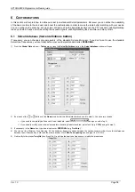
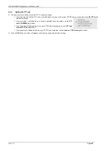
In this section we’ll explain how to define personal (non-standard) Selcall parameters. Moreover you can define the availability 
of the basic controls to the end user and boost the customization in order to make the radio better matching with your needs. 
You can configure the scanning, set up some controls such as the transmission timeout, the PTT lock and enabling/disabling 
the key and warn beeps as well as setting the acoustic signals, enabling/disabling the scrambler and many others. 

6.1  Selcal database (Selcal definitions button) 

If necessary, you can change some parameters of the standard Selcals. Moreover, if you don’t want to use the standard 
Selcal tone frequencies, you can totally define your own Selcal standard called 

PERSONAL

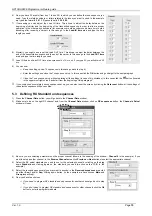
1) From 

the 

Global Data

 window – 

Tables

 area - press the 

Selcal


Definitions 

button: the 

Selcal database

 window will open. 

2) 

By means of the 


 or 

 buttons of the 

Name

 area, select the Selcal standard you need to modify. You have two choices


if you need to completely define a new Selcal standard, select 

 and go on with step 3)  


if you need to modify some allowed parameters of existing Selcal standards,

 just select it (e.g. 

CCIR

) and go to step 7) 

3)  If necessary, in the 

Name

 box, type a new name over 

PERSONAL

 (e.g. 

FireCorp

4)  You can set the 

Minimum Tone Spacing

. It’s the minimum frequency space between the various tones in order to avoid interferences 

between them if decoded by a old (and too wide) decoder. Go to 

Min. Tone spacing

 box and type 10 or 100 Hz. 

5)  Go directly to the proper 

Freq (Hz)

 box (from 0 to F) and type the new tone frequency or modify the preset ones. 

Summary of Contents for HP106

Page 1: ...ALAN HP 106 SERVICE MANUAL...

Page 2: ...HP106 Service Manual Page 1 of 12 ALAN HP106 Portable VHF Transceiver Service Manual Copyright 2003 by CTE International Italy all rights reserved...

Page 3: ...Audio Circuits 6 2 4 e Audio Processing 6 2 5 Receiver 6 2 5 a Receiver Front End 6 2 5 b Local Oscillator LO 6 2 5 c Mixer 6 2 5 d FM Detector and Squelch 6 2 5 e Receiver Audio Circuit 7 2 6 Signall...

Page 4: ...erature Range C from 30 to 60 Transmitter Output Power 1 dB W 1 5 from 9 KHz to 1 GHz 0 25 Spurious Emissions W from 1 to 4 GHz 1 Modulation System F3E FM Modulation KHz 2 5 5 Audio Distortion 5 or le...

Page 5: ...nsated Crystal Oscillator TCXO The reference oscillator X401 is a temperature compensated crystal oscillator RV402 is used to adjust the oscillator on frequency 14 4 MHz at room temperature 22 The ref...

Page 6: ...bled while the loop remains out of lock 2 3 d Loop Filter The Loop Filter a passive lead lag filter consisting of R461 R464 and C493 C495 integrates the charge pump output to produce the DC turning vo...

Page 7: ...output of the low pass filter is coupled C411 to the first band pass filter C412 C415 C417 C420 L404 L407 and to the Front End RF overload protection diode pair Q403 The signal from the band pass fil...

Page 8: ...ut The CTCSS tone signal is adjust to the proper level by RV202 The DCS signal is adjust to the proper balance by RV203 The signal is then applied to the audio processing circuit at R305 and to the TC...

Page 9: ...uits of the radio When the Radio is on a channel with no tone programmed the BATTERY SAVER Mode is enabled when programmed In the BATTERY SAVER mode the microprocessor IQ9 generates a square wave sign...

Page 10: ...transmitter and adjust RV402 for a Frequency Counter reading within 50Hz of the programmed transmit frequency 3 3 Transmitter Alignment NOTE In order to obtain proper transmission output power connec...

Page 11: ...n the following minimum maximum deviation according to the channel bandwidth For 12 5 KHz channel bandwidth min 1 5 KHz max 2 5 KHz For 25 KHz channel bandwidth min 2 5 KHz max 3 KHz 3 4 Receiver Alig...

Page 12: ...05 2 7 5VDC Supply 3 A 3 3 Amp DC Ammeter 4 AC Voltmeter 5 Distortion Meter 6 Test Adapter Figure 2 7 Audio Signal Generator 600 Ohm 8 RF Signal Generator 9 Wattmeter 10W 10 30 dB Attenuator 11 UHF Fr...

Page 13: ...HP106 Service Manual Page 12 of 12 3 6 Figure 2 Test adaptor...

Page 14: ......

Page 15: ...HP406 Service Manual Page 1 of 12 ALAN HP406 Portable VHF Transceiver Service Manual Copyright 2003 by CTE International Italy all rights reserved...

Page 16: ...Audio Circuits 6 2 4 e Audio Processing 6 2 5 Receiver 6 2 5 a Receiver Front End 6 2 5 b Local Oscillator LO 6 2 5 c Mixer 6 2 5 d FM Detector and Squelch 6 2 5 e Receiver Audio Circuit 7 2 6 Signall...

Page 17: ...rature Range C from 30 to 60 Transmitter Output Power 1 dB W 1 5 from 9 KHz to 1 GHz 0 25 Spurious Emissions mW from 1 to 4 GHz 1 Modulation System F3E FM Modulation KHz 2 5 5 Audio Distortion 5 or le...

Page 18: ...Compensated Crystal Oscillator TCXO The reference oscillator X401 is a temperature compensated crystal oscillator RV402 is used to adjust the oscillator on frequency 14 4 MHz at room temperature 22 T...

Page 19: ...while the loop remains out of lock 2 3 d Loop Filter The Loop Filter a passive lead lag filter consisting of R461 R464 and C493 C495 integrates the charge pump output to produce the DC turning voltage...

Page 20: ...put of the low pass filter is coupled C411 to the first band pass filter C811 C818 C822 L404 L407 and to the Front End RF overload protection diode pair D9 The signal from the band pass filter is appl...

Page 21: ...which makes the signals closer to the theoretic CTCSS DCS signals The waveform is then smoothed by low pass filters Q213B to produce an acceptable sine wave output The CTCSS tone signal is adjust to t...

Page 22: ...he BATT SW line by means of R51 R49 When the battery voltage is approximately 5 8V the microprocessor considers the battery discharged and switches off the circuits of the radio When the Radio is on a...

Page 23: ...transmitter and adjust RV402 for a Frequency Counter reading within 50Hz of the programmed transmit frequency 3 3 Transmitter Alignment 2 NOTE In order to obtain proper transmission output power conn...

Page 24: ...n the following minimum maximum deviation according to the channel bandwidth For 12 5 KHz channel bandwidth min 1 5 KHz max 2 5 KHz For 25 KHz channel bandwidth min 2 5 KHz max 3 KHz 3 4 Receiver Alig...

Page 25: ...06 2 7 5VDC Supply 3 A 3 3 Amp DC Ammeter 4 AC Voltmeter 5 Distortion Meter 6 Test Adapter Figure 2 7 Audio Signal Generator 600 Ohm 8 RF Signal Generator 9 Wattmeter 10W 10 30 dB Attenuator 11 UHF Fr...

Page 26: ...HP406 Service Manual Page 12 of 12 3 6 Figure 2 Test adaptor...

Page 27: ...ALAN HP 106 PCB LAYOUTS AND TEST POINTS...

Page 28: ......

Page 29: ......

Page 30: ......

Page 31: ......

Page 32: ......

Page 33: ......

Page 34: ......

Page 35: ......

Page 36: ......

Page 37: ...HP106 HP406 Programmer software guide Ver 1 0 Page 1 HP106 HP406 VHF UHF Handheld Transceiver Programmer Software Guide Ver 1 0 issued on June 15th 2003...

Page 38: ...3 by CTE International Italy all rights reserved Microsoft MS and Windows are registered trademarks of Microsoft Corporation IBM is a registered trademark of International Business Machines Corporatio...

Page 39: ...omers You should be familiar with conventional radio systems radio system and radio network settings parameters as well as general PC operation This programming guide is subject to change without noti...

Page 40: ...default TX calls and Auto ID ANI 16 5 5 Monitor Key Behaviour 16 5 6 Manual Autoreset for selective calls 17 5 7 Overviewing a Channel Data Summary 17 6 CUSTOMIZATIONS 19 6 1 Selcal database Selcal d...

Page 41: ...ert the CD with the software in your drive 3 Click the Start button click Run you will see the Run dialog box 4 Type D setup exe where D indicates your CD drive or click the Browse button and use the...

Page 42: ...access the connectors 4 Insert the end of the supplied serial cable provided with 2 5 mm stereo jack plug B in the 2 5 mm jack socket of the transceiver C 5 Push gently the cable s 2 5 mm stereo jack...

Page 43: ...om 2 the tick will be moved on Com 2 and this port will be switched as default 3 3 Checking the software version If you want to see the software version and other additional info from the menu Help se...

Page 44: ...abase name you want to create any name will do anyway we recommend to type the customer s name then press the Save button the Channel Data window will open Important we ll always refer this window as...

Page 45: ...be immediately available Tick it if you want to designate the channel as priority one Obviously you can designate only one priority channel If you already did that with another channel a message will...

Page 46: ...e CTCSS decoder as well click on the RX tone Hz drag down button and select the tone decoding frequency you need e g 103 5 Hz If in you need to set up the same RX and TX tone frequency just click on t...

Page 47: ...tching between Channel Data and Global Data windows Starting from now we ll need to switch between Channel Data and Global data Windows Global data window can be recalled at any time by clicking the G...

Page 48: ...e Set Up 2 area is useful to set up additional parameters such as the emergency call and the power save ones For further information please see the paragraphs 6 9 and 6 10 The Tables area allows you t...

Page 49: ...area and press the or button to select the Rx sequence you need to setup In the following example we selected the sequence 1 4 If you want to assign an alphanumeric name to the selected Rx sequence j...

Page 50: ...ings in case of big mistakes In this case click the button located in the uppermost right corner and start from the beginning of this paragraph If you composed a completely wrong sequence set up you c...

Page 51: ...all the settings in case of big mistakes In this case click the button located in the uppermost right corner and start from the beginning of this paragraph If you composed a completely wrong sequence...

Page 52: ...also set the time which the radio has to wait before sending the transpond sequence just set if the channel is busy Just go to the Wait before transpond on BUSY Channel drag down button and select th...

Page 53: ...the Autoreset window will open 4 Select the autoreset time you need by clicking the Autoreset drag down button and then click the needed time You can select a time from 5 to 155 sec in 5 sec steps or...

Page 54: ...ton It will remain on the screen providing an useful programming monitor In fact it can be manually updated every time you press the Update button or automatically after any programming operation you...

Page 55: ...one frequencies you can totally define your own Selcal standard called PERSONAL 1 From the Global Data window Tables area press the Selcal Definitions button the Selcal database window will open 2 By...

Page 56: ...n the PTT Pressing while scan area you can define the channel in which the radio should transmit if PTT is pressed during scan Select the Priority First scan channel radio button if you need the trans...

Page 57: ...pert users TX timeout defines the maximum transmission time available for the end user for every message If he she continuously presses the PTT and reaches a certain preset time the TX will be momenta...

Page 58: ...e NO PTT Lock radio button active If you need the Tx inhibited when a carrier is detected busy channels use the PTT lock if CARRIER radio button If you need the Tx inhibited when the correct CTCSS ton...

Page 59: ...s acoustic signals Each ring is composed by a preset number of bursts from 1 to 255 Each burst is obtained by alternating two tones Tone 1 and Tone 2 a preset number of times Let s call each alternati...

Page 60: ...ck the new ring obtained You have several choices If you need to provide other modifications to the current ring go back to step 4 If you need to change another ring go back to step 2 If you want to e...

Page 61: ...eceiver at regular times during stand by no signals received If a signal is received during work state the power save cycle is interrupted and will be resumed again after a certain time in which the s...

Page 62: ...PLOAD_RX_SEQ_DEF x These two messages are repeated for each RX channel x is the number of the uploaded RX channel UPLOAD_TX_SEQ_DEF x These two messages are repeated for each TX channel x is the numbe...

Page 63: ...e 1 From the menu Options select Restore System DB A window will open with the message Restore the SYSTEM DB Default Public Data CTCSS Definition and Selcal Definition 2 Press OK to restore the System...

Page 64: ...ing the directory tree in folder box programming files use the extension hpv or hpu and are usually placed in the directory C Programs HPx06 usrDB 5 As soon as you have selected the appropriate file n...

Page 65: ...ckage contents 5 System requirements 5 M Manual Autoreset for selective calls 17 Monitor Key Behaviour 16 N New or already stored data 7 P Power save function 25 Programming modifying an already progr...

Page 66: ...ndition 20 scanning timing speed priority wait 20 scanning with CTCSS DCS 20 scanning with Selcal 20 Tx PTT resume timer 21 Tx timeout timer 21 wrong CTCSS Tx lockout 22 Software installation 5 T Tran...

Page 67: ...ALAN HP 106 ELECTRICAL DIAGRAMS...

Page 68: ......

Page 69: ......

Page 70: ......

Page 71: ......

Page 72: ......

Page 73: ...ALAN HP 106 EXPLODED VIEW AND PART LIST...

Page 74: ......

Page 75: ...6 907 020 Felt Speaker FELT T0 3 1 1 7 420 127 6 Speaker 40 8BB 24F 1 1 8 600 814 Screw PH M2x5 Blk H T1 1 2 1 9 632 006 Screw BH BLK T2 4 1 2 0 772 516 Shield can C SPTE TO 3 1 2 1 772 514 Shield ca...

Page 76: ...ilicone Rubber 1 4 6 95A 820C Label Battery Polyester 39 5x 34 5 1 46 1 895 833 Gasket Battery Gore Tex T0 2 1 4 7 733 004 Battery Holder SUS T0 4 1 4 8 719 897 Cover Top Batt P C 1 4 9 753 124 Termin...

Page 77: ...X10 3XT0 25 FIBER 2 EA 3 906 857 DOUBLE TAPE 34X10XT0 16 3M 1 EA 3 907 043 DOUBLE TAPE FOR BATT3M 26X10XT0 16 1 EA 3 2 577 59B A1 BATTERY ASS Y 1 EA 3 95A 820 LABEL BATTERY POLYESTER 39 5X34 5 1 EA 6...

Page 78: ...6 59 69 84 92 99 320 54 8 429 38 44 7 52 94 556 3 05B 104 6Z CHIP RESISTOR 100K 1 16W 5 T 1608 2 8 EA R1 2 3 10 11 13 14 16 17 18 19 30 33 39 151 210 45 68 302 3 7 57 434 5 58 78 99 RZ402 3 05B 105 7Z...

Page 79: ...226 7 9 230 234 287 97 310 6 8 20 30 1 53 3 130 A75 8Y CHIP CERAMIC 0 001UF GRM39 X7R102K 50V PT 7 2 EA C101 8 12 18 20 36 8 56 65 73 76 201 4 7 20 39 40 2 4 8 50 5 6 7 60 1 8 9 77 84 5 93 4 6 321 4...

Page 80: ...50V PT 1 EA C271 3 140 114 3Y CHIP TANTALUM 0 1UF TCM1V104ASSR 35V 2 EA C493 494 3 140 204 1 CHIP TANTALUM 0 22UF 293D224X0035A2T35V 1 EA C283 3 141 036 1 CHIP TANTALUM 1UF 293D105X0016A2T16V 7 EA C2...

Page 81: ...IH10TR10JNC 4 EA L416 420 421 422 3 311 797 8 COIL CHIP 39NH LQN21A39NJ04 2 EA L425 427 3 312 018 3 COIL AIR WOUND LE 017 2 5D 4T 0 5 2 EA L401 402 3 312 019 4 COIL AIR WOUND LE 019 2 5D 5T 0 5 1 EA L...

Page 82: ...424 7 ANTENNA SXB 165MX BLACK 162 174MHZ 1 EA 3 91C 002 PAD TRC 439 SW1S 268X21 1 EA 3 91D 012 BOX INNER UK SW1S 230 W X210 D X102 H 1 EA 3 91D 020 PAD A SW1E 399X381 1 EA 3 91D 021 PAD B SW1E 612X24...

Page 83: ......

Page 84: ......

Page 85: ...Knob Vol ABS 1 14 1 826 449 Knob Ch ABS 1 15 895 793 Lens LED Silicone Rubber 1 16 907 020 Felt Speaker FELT T0 3 1 17 420 127 6 Speaker 40 8BB 24F 1 18 600 814 Screw PH M2x5 Blk H T1 1 2 19 632 006 S...

Page 86: ...Silicone Rubber 2 44 702 484 Frame Main AL Ni Plate 1 45 895 790 Gasket Main Silicone Rubber 1 46 95A 820C Label Battery Polyester 39 5x 34 5 1 46 1 895 833 Gasket Battery Gore Tex T0 2 1 47 733 004 B...

Page 87: ...BATTERY NI MH GP130AAM6SXZ 1 EA B SUB BATT 04 01 06 3 719 897 A COVER TOP BATT PC 1 EA B SUB 03 03 26 3 719 898 A COVER BOTTOM BATT PC 1 EA B SUB 03 03 26 3 733 004 A HOLDER BATTERY SUS T0 4 1 EA B SU...

Page 88: ...A CT04 0544 5 930 1 78 95 6 3 221 777 2 POWER MODULE RA07M4047M 1 EA B SUB U Q407 04 01 14 C CT04 PAT 3 263 469 6 CRYSTAL UM 6S 44 645M 30 15PM 13 8P 1 EA B SUB X201 04 01 06 3 263 477 3 CRYSTAL 8MHZ...

Page 89: ...36 3 05B 224 1Z CHIP RESISTOR 220K 1 16W 5 T 1608 3 EA B SMD R305 353 950 04 08 23 C CT04 0748 3 05B 229 6Z CHIP RESISTOR 2 2 1 16W 5 T 1608 1 EA B SMD R257 04 01 14 C CT04 PAT 3 05B 272 4Z CHIP RESIS...

Page 90: ...094 5 208 209 217 222 236 241 270 301 323 325 508 CZ402 3 130 249 9 CHIP CERAMIC 0 0022UF GRM39 X7R222J 50V PT 2 EA B SMD C223 267 04 08 23 C CT04 0748 3 130 290 5Y CHIP CERAMIC 0 22UF GRM40 X7R224K 1...

Page 91: ...5 6PF GRM39 COG5R6C 50V PT 3 EA B SMD C830 836 993 04 01 14 C CT04 PAT 3 136 014 3Y CHIP CERAMIC 6PF GRM39 COG060D 50V PT 6 EA B SMD C436 813 831 837 980 991 04 09 07 C CT04 0816 3 136 838 1Y CHIP CER...

Page 92: ...803 2 I C ANALOG MULTIDLEX 74VHC4053 2 EA B SMD IC Q3 16 04 01 14 A CT04 PAT 3 221 847 2 I C MICRO CONTROLLER MSP430F149IPM 1 EA B SMD IC Q17 04 06 30 C CT04 0581 3 241 252 0 DIODE UDZTE 175 1B 1 EA...

Page 93: ...03 26 3 702 484 FRAME MAIN AL NI PLATE 1 EA B SUB 03 03 26 3 719 895 A COVER ANT FIXER PC 1 EA B SUB 03 03 26 3 895 790 GASKET MAIN SILICONE RUBBER 1 EA B SUB 03 03 26 3 895 796 GASKET PORON T0 8 1 EA...

Page 94: ...ER 45X20 1 EA B FIN 04 07 21 A CT04 0639 3 95B 102 LABEL RTTE COUNTRY ARTPAPER 90X15 1 EA B FIN 04 07 21 A CT04 0639 3 95B 131 LABEL CE ARTPAPER 33X8 1 EA B FIN 04 07 21 A CT04 0639 3 95B 157 A LABEL...

Reviews: