10
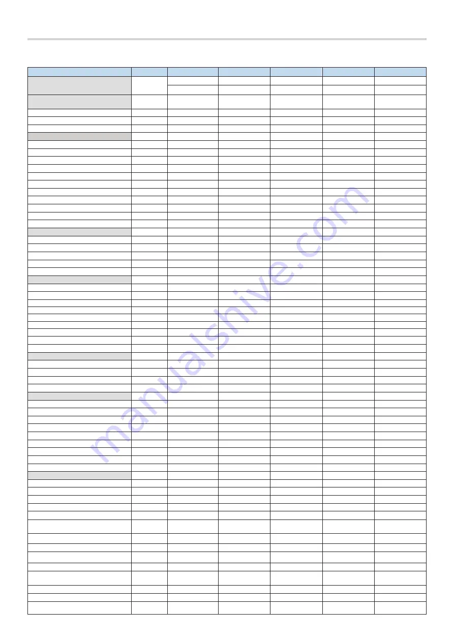
2.2. Technical Specifications
PROPERTY
UNIT
ALDENS 65
ALDENS 85
ALDENS 105 ALDENS 130 ALDENS 150
Types Proper for Cascade Setup
Master (L)
Master (L)
Master (L)
Master (L)
Master (L)
Slave (T)
Slave (T)
Slave (T)
Slave (T)
Slave (T)
Fuel
Natural Gas (G20) +
LPG (G31)
Natural Gas (G20) +
LPG (G31)
Natural Gas (G20) +
LPG (G31)
Natural Gas (G20) +
LPG (G31)
Natural Gas (G20) +
LPG (G31)
Upstream Pressure (Inlet)
mbar
21
21
21
21
21
Fuel Consumption @ Maximum Load
m
3
/h
6,87
8,83
11,17
13,28
15,11
Fuel Consumption @ Minimum Load
m
3
/h
1,35
1,76
2,16
2,68
3,07
Technical Parameters wrt. ErP Directive
P
n
– Rated Heat Output
kW
64
85
105
125
145
P
4
– Useful Heat Output @ Max L.– (80/60
o
C)
kW
61,6
81,2
101,3
120,0
143,7
P
1
– Useful Heat Output @ Part L. – (50/30
o
C)
kW
20,7
25,3
34,2
41,0
46,0
η
s
– Seasonal Space Heating Energy Efficiency
%
91
93
92
94
91
η
4
– Useful Efficiency @ Max L. – (80/60
o
C)
%
87,3
86
86,9
86,4
89,2
η
1
– Useful Efficiency @ Part L. – (50/30
o
C)
%
97,7
97,5
97,7
98,4
96,7
P
stby
– Standby Heat Losses
W
68
80
80
117
121
P
ign
– Ignition Burner Energy Consumption
kW
1,75
2,92
1,97
1,94
2,16
L
wA
– Sound Power Level (Indoors)
dB
58,8
61,9
63,8
66,3
67,4
NOx – Emissions of Nitrogen Oxides
mg/kWh
44,2
46,2
41,3
55,2
54,6
NOx Class
-
6
6
6
6
6
Boiler Heat Output / Efficiency
Maximum / Minimum Output (50/30
o
C)
kW
67,2 / 13,4
90,1 / 18,5
109,0 / 21,7
135,1 / 27,3
153,9 / 30,7
Maximum (P
4
) / Minimum Output (80/60
o
C)
kW
61,6 / 12,0
81,2 / 16,5
101,3 / 19,5
120,0 / 24,5
143,7 / 28,2
Output @ Fan Ignition RPM
kW
27,5
44,3
52,2
56,8
60,1
Efficiency (
50/30
o
C – Max./ Min. Load
)
%
105,8 / 107,3
106,0 / 108,6
103,9 / 108,3
108,1 / 109,0
106,2 / 105,8
Efficiency (
80/60
o
C – Max./ Min. Load
)
%
97,0 / 95,8
95,6 / 97,2
96,5 / 97,6
96,0 / 97,8
99,1 / 97,2
Maximum Backpressures / Fluegas Flowrate
Backpressure (Max. / Min. Load)
Pa
137 / 79
210 / 105
253 / 90
256 / 70
282 / 87
Backpressure (Ignition)
Pa
106
116
122
106
118
Fluegas Flowrate (Maximum Load - 50/30
o
C)
g/s
24,7
34,9
44,6
51,8
58,2
Fluegas Flowrate (Minimum Load - 50/30
o
C)
g/s
4,9
7,0
8,6
10,5
11,8
Fluegas Flowrate (Maximum Load - 80/60
o
C)
g/s
30,0
37,7
48,4
57,1
64,2
Fluegas Flowrate (Minimum Load - 80/60
o
C)
g/s
5,9
7,5
9,4
11,5
13,0
CO
2
Conc. (Max. / Min Load) – (50/30
o
C)
%
9,12 / 9,12
9,0 / 9,0
9,05 / 9,16
9,13 / 9,23
9,27 / 9,06
Flue Temp. (Max. / Min. Load) – (50/30
o
C)
o
C
63,3 / 40,4
51,6 / 34,2
64,8 / 32,1
58,0 / 31,7
54,4 / 43,8
Flue Temp. (Max. / Min. Load) – (80/60
o
C)
o
C
82,7 / 64,1
70,0 / 62,7
78,0 / 60,8
74,8 / 60,5
74,5 / 65,0
Electrical Properties
Electrical Input (Voltage/Frequency)
VAC/Hz
230 / 50
230 / 50
230 / 50
230 / 50
230 / 50
Electrical Fuse
A
6,3
6,3
6,3
6,3
6,3
Electrical Consumption in Standby
W
2,7
2,7
2,7
2,7
2,7
Electrical Consumption – Max. / Min. Load
W
91,8 / 18,7
109,0 / 14,7
131,1 / 16,9
205,7 / 18,8
284,2 / 21,0
Installations / Connections
Gas Connection
inch
¾”
¾”
¾”
¾”
¾”
Heating Circuit (Inlet / Outlet)
inch
1”
1 ¼”
1 ¼”
1 ¼”
1 ¼”
DHW Circuit (Inlet / Outlet)
inch
1”
1 ¼”
1 ¼”
1 ¼”
1 ¼”
Maximum Water Pressure of Operation
bar
4,5
6
6
6
6
Minimum Water Pressure of Operation
bar
1
1
1
1
1
Boiler Hydraulic Loss – Max Load (50/30
o
C)
mWC
5,4
2,9
4,4
5,0
5,0
Boiler Hydraulic Loss – Max Load (80/60
o
C)
mWC
4,6
2,5
3,7
3,9
4,5
Water Flowrate @ Max. Load - (50/30
o
C)
m
3
/h
2,8
3,7
4,5
5,6
6,3
Boiler water fill up volume
lt
3,4
6,6
6,6
8,2
10,1
General Properties
Boiler Net Dimensions (W x D x H)
mm
493 x 540 x 627
493 x 540 x 797
493 x 540 x 797
493 x 540 x 797
493 x 635 x 797
Packaged Dimensions (W x D x H)
mm
565 x 740 x 760
565 x 910 x 760
565 x 910 x 760
565 x 910 x 760
565 x 910 x 850
Boiler Weight (Empty / Full)
kg
54,6 / 58
68,7 / 75,3
68,7 / 75,3
75,2 / 83,4
88,6 / 98,7
Packaged Weight
kg
58,6
72,7
72,7
79,2
92,6
Chimney Pipe Diameters (exhaust/air intake)
mm
100 / 150
100 / 150
100 / 150
100 / 150
100 / 150
Type
-
Hermetic / full
condensing
Hermetic / full
condensing
Hermetic / full
condensing
Hermetic / full
condensing
Hermetic / full
condensing
Control Panel
-
Electronic and Push
Button
Electronic and Push
Button
Electronic and Push
Button
Electronic and Push
Button
Electronic and Push
Button
Ignition System
-
Electronic
Electronic
Electronic
Electronic
Electronic
Fault Detection and Warning
-
YES - error code on
screen
YES - error code on
screen
YES - error code on
screen
YES - error code on
screen
YES - error code on
screen
Floor Heating Application
-
YES
YES
YES
YES
YES
Cascade Operation
-
256 items
maximum
256 items
maximum
256 items
maximum
256 items
maximum
256 items
maximum
Frost Protection
-
YES
YES
YES
YES
YES
Time Programming / Holiday Mode
-
YES
YES
YES
YES
YES
Parametric Tuning Hardware
-
User monitor HMI
/ PC
User monitor HMI
/ PC
User monitor HMI
/ PC
User monitor HMI
/ PC
User monitor HMI
/ PC
Summary of Contents for ALDENS 105
Page 1: ...ALDENS 65 85 105 130 150 L T USER MANUAL ...
Page 2: ...Code No A 4 1 14i Publishing Date 180121 Revision Date 180121 ...
Page 3: ...ALDENS 65 85 105 130 150 L T USER MANUAL ...
Page 6: ...6 ...
Page 24: ...24 ...
Page 71: ...71 ...
Page 72: ...72 ...
Page 73: ...73 ...
Page 74: ...74 ...
Page 75: ...75 ...


