The ALM Series burners receive the air for combustion via the air suction chamber. After passing
through this air suction chamber, the combustion air enters into the burner and reaches the
combustion head mixing point via a fan operating in the volute shaped casing. The mixing point
consists of the air diffuser and the combustion head. Here, the fuel injected by the nozzle mixes with
air to form an ideal burning mixture. This way, smooth combustion and maximum fuel savings are
obtained.
7
PRINCIPLES OF OPERATION
BURNER
TYPE
CAPACITY
(kg/h)
HEAT OUTPUT
MOTOR
WEIGHT
(kg)
POWER SUPPLY
kW
Kcal/h
Min.
Max.
Min.
Max.
Min.
Max.
Speed(rpm) Power(kW)
ALM 125/2
53,4
125
632,8
1482
544.680 1.275.000
2850
2,2
66
3~380..400V-50Hz
ALM 174/2
60,5
174,7
717
2071
617.100 1.781.940
2850
3
66
3~380..400V-50Hz
Lower calorific value of the fuel: 10.200 kcal\kg
TECHNICAL SPECIFICATIONS
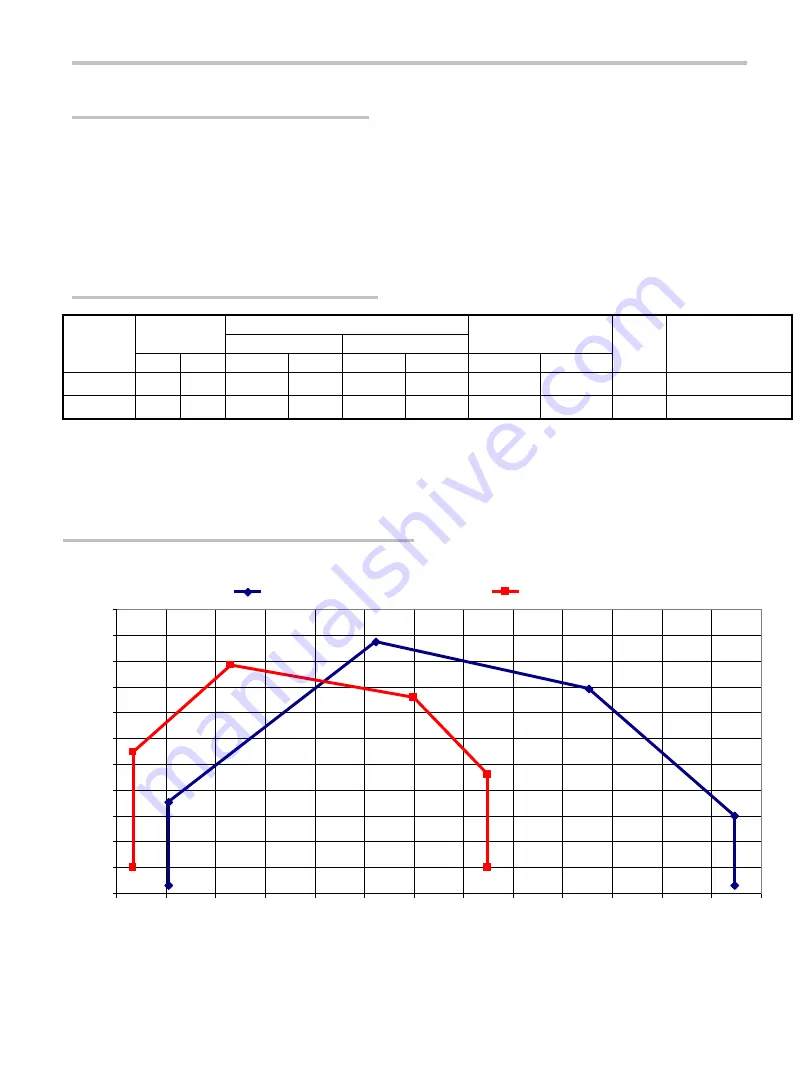
CAPACITY – PRESSURE CURVES
NOTE :
The operation diagram above shows the desired fuel consumption in the combustion chamber as
a function of pressure. The fuel consumption and pressure values represent the values obtained by the
burner to meet the requirements of EN 267.
-1
0
1
2
3
4
5
6
7
8
9
10
50
60
70
80
90
100
110
120
130
140
150
160
170
180
Capacity (kg/h)
C
h
a
m
b
e
r
P
re
s
s
u
re
(
m
b
a
r)
ALM 174/2
ALM 125/2


