5
tery connector and battery pack outside its compart-
ment, proceed as follows:
6. Stand the lock
in the upright position.
6a.
On the back of the DL lock,
locate the Roll Pin
that
holds the Tailpiece to the Hub. Rotate the Hub/
Tailpiece assembly until the Roll Pin is in the
hori-
zontal
position.
6b.
At the lock keypad, enter a valid User Code
. For
new locks, enter the default Master Code (use
"12345" for the DL1200ET; use "123456" for the
DL1300ET and PDL1300ET). Entering the Code
engages the lock mechanism and draws the Hub
into DL lock housing about 5/32".
Immediately disconnect the battery plug
, thus
retaining the mechanism in the engaged ("fixed")
position, unable to rotate. With the Tailpiece now
unable to rotate freely, the remaining steps can be
performed more easily.
6c.
Look down the length of the Tailpiece
to observe
its "front view". Verify that the cross-shaped Tail-
piece is in the vertical and horizontal position (+)
and the Tailpiece can only rotate when the lever is
turned. If the Tailpiece is not correctly positioned,
manually rotate the Tailpiece until it "clicks" into the
engaged position and is unable to rotate.
6d.
Apply a film of oil
to the front of the Tailpiece.
Place the DL lock on the door, inserting the Tail-
piece into the "Receiver" (or "keyway") of the exist-
ing exit device. Verify the shaft of the Tailpiece
floats inside the exit device Receiver (the Tailpiece
must move in and out of the Receiver freely).
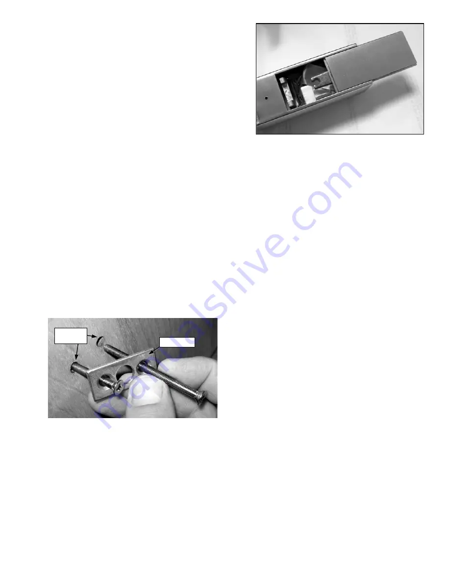
6e.
Secure the DL lock to the door
with four (4)
through-door mounting screws and two Door Plates
as follows: Insert a mounting screw into one of the
two Door Plate holes. Inside the door, insert the
mounting screw into the door thru-holes, carefully
threading the mounting screw into the DL lock hous-
ing by hand (see Fig. 6e). Repeat for three remain-
ing mounting screws. Snug all four mounting
screws before final tightening--do not over-tighten.
6f.
Plug in the battery connector and insert the battery
pack into the battery compartment. Neatly push all
wiring inside the compartment.
Holding battery in
place
, slide cover back on. Secure the battery cover
by tightening the #8-32 Phillips pan head screw lo-
cated on the rear side of the base plate (access this
screw from the 7/16" thru-hole drilled in the door in
step 3a).
Do not over tighten the screw
. Upon con-
necting the battery power, the DL lock disengages.
6g.
Install the decorative Door Plate Covers by sliding
them--in a vertical direction from top to bottom--over
the installed Door Plates.
Programming the Lock
Refer to programming instructions (WI1686, WI1687
or WI1688) for specific instructions for "First Time
Startup" and "Change Factory Master Code" before
connecting the battery.
The lock must be powered up correctly (and have its
factory Master Code changed) or erratic lock behav-
ior can result.
Fig. 6f: Install the battery pack: Push all wires inside the battery
compartment and slide plate back on.
Fig. 6e: Insert mounting screws into Door Plate holes, then into the
inside door thru-holes.
Door
Thru-Holes
Door Plate
Summary of Contents for DL1200ET
Page 7: ...7 NOTES ...


