background image

r

Glossary

ACCESS  =  To  allow  Users to  unlock the  door temporarily to  gain  en­

try.

AMBUSH  =  A  special  Code  entered  at  the  keypad  when  the  User  is 

forced  to  unlock a  device.  The  device  unlocks  but  sends a  silent 
alarm  with  no  indication  at the  keypad.  Can  be  used  to  trip  a  re­
lay,  to  alert  security,  or  trip  a  silent  alarm  on  a  Burglary  Control 

Panel.

AUDIT TRAIL = A date/time stamped  log of previous lock events.

BUTTON  PRESS  =  A  button  control  on  the  DL4100  series  locks  pre­

venting access to outside  Users.

BURGLARY  CONTROL  PANEL  =  Provides  local  alarm  and  remote 

communication  to  request  security  for  burglary/break-in. 

DL4500  relay  output  used  for  Ambush  can  provide  a  silent  alarm 

and call-for-help.

CANCEL  PASSAGE  ON  DEADBOLT/BUTTON  PRESS  =  A  lock 

function  in  the  "Residency"  Feature  that  will  prevent  passage 

through  the  door  (for  Users without  a  functional  User  Code)  after 

extending the deadbolt or pressing the  button.

CLO C K

•   REAL  TIME  CLOCK  =  An  accurate  built-in  clock  that  allows 

date/time  stamping  of  events.  The  clock  can  be  slowed  or 
speeded  up  to  fine  tune  long  term  accuracy  to  within  three 

minutes per year.

•   CLOCK  SETTINGS  =  Printout  includes  date,  time,  weekday, 

and clock speed.

•   CLOCK  SPEED  =  The  clock  can  be  adjusted  to  allow  faster/ 

slower speeds and therefore  increasing clock accuracy.

CODE  =  Numeric  sequence  of  numbers  (such  as:  1234)  entered  at 

the  keypad.  If Star-Enter-Key  is  required,  must  be  followed  by  a 

fl ^

1

l  key.

•   AMBUSH CODE  = See Ambush.

•   BASIC  USER  CODE  =  User  Codes  assigned  to  User  Num­

bers  12+  (except  Users  297-300). 

(Does  not  allow 

programming)

•   INSTALLER  CODE  =  User Codes assigned  to  User  Numbers

2 and 3.  (Allows all  programming except Master functions).

•   INVALID  CODE  =  A  User  Code  that  has  not  been 

programmed  in the  lock.

•  

MANAGER  CODE  =  User Codes assigned to  User Numbers 4 

through 

6

.  (Allows most of the programming functions).

•  

MASTER  CODE  =  User  Code  assigned  to  User  Number  1. 
Default  (factory)  Master  Code  is  123456.  The  User  with  the 
Master Code  has complete control of the  lock.

•   PRINT  ONLY  USER  CODE  =  User  Code  assigned  to  Users 

10 and  11.  (Allows no programming except print functions).

•   QUICK  ENABLE  USER 300  CODE  =  Refers to the  User Code 

entered  by  User  297  which  (when  entered  at  the  keypad)  en­
ables the  User Code assigned to  User 300 for one time only.

•   QUICK  PC  ACCESS  CODE  =  Permits  upload/download  to 

DL-Windows  Software  on  IBM/compatible  (300  MHz  or faster)

computer running  Microsoft Windows 98,  or  NT 4.0 (or higher). 

Refers to the  User Code for User 298.

•   SERVICE  CODE  =  User  300  User  Code.  Allows  only  one 

entry, then  needs to  be  re-enabled  by the  User 297  User Code 
to  regain access.

•   SUPERVISOR  CODE  =  User  Codes  assigned  to  Users  7, 

and 9.  Can only program day-to-day operation.

•   USER  CODE  =  Code  used  by  Users.  Code  is 3 to 

6

  numeric 

digits long, allowing controlled entry.

•   VALID  CODE  =  An  entered  User  Code  that  has  been 

programmed  in the device.

COM  PORT  =  A  computer  serial  communications  port  used  to 

communicate with the  Lock and/or Data Transfer Module.

DATA  TRANSFER  MODULE  =  A  device  that  permits  transfer  of 

program/data  between a computer and the  lock.

DATE =  Month,  Day and Year entered as MMDDYY.

DAY  OF  WEEK = Sunday through  Saturday (where  1  = Sunday and 7 

=  Saturday).

DEFAULT =  Default  settings are  the  original  settings that  were  set  at 

the  factory;  in  other words,  it  is the  lock's original  factory condition 
when  the  lock  was  first  taken  out  of its  box.  The  default  settings 

are  permanently  encoded  within  the  lock's  fixed  memory,  and 

when  the  lock  is  first  started,  or  when  power  is  removed  and  re­

applied  (see  Wiring  and  Power-Up,  page  11),  the  original  factory 
default settings are  re-loaded and take effect.

DISABLE  = Turn off.

DISABLE  KEYPAD  ON  DEADBOLT /  BUTTON  PRESS  = A feature 

of the  "Privacy"  feature  that  disables the  keypad  (except  for  User 

Numbers  1-11)  when  the  deadbolt  is  extended  or  the  button  is 

pressed.

DOOR  NUMBER  =  Identification  of each  door with  a  specific  number 

(1-96).  (Used with AL-DTM2 Transfer Module)

DOWNLOAD =  Send data to  lock or AL-DTM.

ENABLE  = Turn on.

EVENTS  =  Recorded  lock activity.

FACTORY DEFAULT =  See  Default.

FUNCTION  (also called  Programming  Functions)  = are the  numbers 

used  to  program  lock  features  (enabling/disabling  Users,  User 
Groups,  Passage  Mode,  Schedules,  etc.).

GROUP

• 

USER GROUP  =  Defining a  User to specific Groups,  allows 
User entry when the  Group is allowed entry.

• 

GROUP  1  DISARMS  BURGLAR  CONTROL  =  A  Group  1 

USER  CODE  entry  can  disarm  an  alarm  panel  during  a 
predefined  schedule. 

Should  the  Group  1  enter  the  lock 

outside  of  the  scheduled  time,  the  alarm  will  not  disarm.  The 
alarm  panel  must  be  armed  through  other  means  (such  as an 
Alarm  Panel  Keypad).  The  Burglary  Alarm  Panel  must  be 

programmed  to  disarm  from  an  Armed  State  Only  and  the 

zone input must be  programmed for input disarming.

36

Summary of Contents for Trilogy DL4100 Series

Page 1: ...ALARM LOCK 2004 Trilogy DL4100 DL4500 Series Programming Instructions _______________________________________________________________ W I1194B 12 04 J DL4500 Residency Lock DL Windows AL DTM DATA TRA...

Page 2: ...acy features and can be program m ed either w ay to suit the installation requirem ents The R esidency feature is specially designed to prevent unintentional lock out typically used in retirem ent hom...

Page 3: ...A utom ated U nlock Lock E nable D isable U sers see page 16 Function 3 E nable D isable G roups see page 17 F our Q uick S chedules contains 4 m ost com m on schedules see page 26 R eal tim e clock...

Page 4: ...CK AL PCI cable is required to communicate between your computer s RS 232 serial com munications port COM 1 4 and the a L DTM or lock One end of the A l PCI cable is designed to be used on a 9 pin ser...

Page 5: ...g you must first enter something called Program Mode What is Program Mode Most technical people find working with hardware easy they use tools to make fixes or changes to hardware But with the soft wa...

Page 6: ...hority a Programming Level as to their ability to use or make changes to the lock The Programming Level defines the range of programming tasks a User is allowed to perform The higher the Level the mor...

Page 7: ...e becomes disabled For example you wish to allow one time access to a temporary worker Simply enter the User 297 User Code into the lock key pad Later when the temporary worker enters the User 300 Use...

Page 8: ...ociated with Users 10 11 Restricted to print audit trails only No other programming ability allowed Abbreviated as Programming Level 1 Basic Users Always associated with User number 12 and higher exce...

Page 9: ...er feedback is as follows ACTIVITY LED SOUNDER COMMENTS Keypress 1 RED Flash 1 Beep Normal Operation Access Granted 3 GREEN Flashes 3 Beeps Invalid Code 6 RED Flashes 6 Beeps Re enter User Code Succes...

Page 10: ...the program in DL Windows and transfer the program from your computer to an AL DTM via an AL PCI cable then transfer the program from the AL DTM to the lock s via a double ended mini banana plug The h...

Page 11: ...h red 6 times and 6 beeps will sound The lock is now ready for use The pre existing program is loaded from fixed memory Set the clock using functions 38 39 and 40 BATTERY REPLACEMENT When a valid code...

Page 12: ...in Program Mode you can now proceed directly below and program various functions Note Programming any Function such as setting the clock follows a consistent 5 step pattern 1 Enter Program Mode 2 Pres...

Page 13: ...urrently open the lock If the lock does not open the anticipated Master Code can be used as the new Master Code if the lock opens the anticipated Master Code already exists in the lock as a User Code...

Page 14: ...tion 19 22 Group 1 4 Enable See page 17 Function 68 Delete All Relay Functions and System Options added by Function 67 Also Privacy Time out duration See page 24 Function 23 Enable All Groups See page...

Page 15: ...on page 6 for more information Lock Defaults for the DL4100 and DL4500 See page 8 Users added will default to a Group Association and a Program Level Ability as follows USER TYPE USER NUMBER GROUP DEF...

Page 16: ...II Ol 11 3 II Ol IIC P lllC P lll 3 11 3 11 311 33 1 IICQl NOTE Up to 4 Timeout Functions may be pending at any one time An error beep will sound when attempting to program more than 4 Timeout Functio...

Page 17: ...nd when attempting to program more than 4 Timeout Functions Important It is the responsibility of the lock programmer to verify the proper lock unlock conditions and Group conditions after programming...

Page 18: ...d Disable Group 1 26 Timed Disable Group 2 27 Timed Disable Group 3 28 Timed Disable Group 4 29 Timed Disable All Groups 30 Timed Enable Group 1 31 Timed Enable Group 2 32 Timed Enable Group 3 33 Time...

Page 19: ...AM Default DST Mode is 12 DST Mode Time Forwarded Time Regressed 01 No DST Adjustment 02 1st Sunday in March 4th Tuesday in Sept 03 Last Sat in March Last Sat in Sept 04 Last Sunday in March Last Sund...

Page 20: ...3 Speed Up Clock 1 1 This Function enabled through keypad only 44 Slow Down Clock 1 1 1 This Function enabled through keypad only 3 ___ 3 seconds 3 ___ 3 seconds PASSAGE MODE Passage Mode Enable Disab...

Page 21: ...oggles Passage Mode Because of firmware conflicts do not use this function with the Residency Feature nor with the Privacy Feature Mode 2 Door Normally Unlocked Mode 3 Group 2 enables Group 3 disables...

Page 22: ...ess 1 for more events or 9 to quit To abort printing press any key for 3 seconds three short beeps will sound 1 56 Print User Code List QQ 1 0 6 1 lied Hold the printer over the lock s infrared sensor...

Page 23: ...ck Program 4 LOCKOUT 60 Number of Attempts Before Lockout _ Number of Attempts Used with Function 61 Number of attempts before lockout must be 1 9 attempts The number of attempts is reduced by half ev...

Page 24: ...her only except 297 298 and 299 Feature 31 should be used with External DC Power unless feature is used for short a duration and infrequently sustained closure of relay will drain batteries ___ ______...

Page 25: ...disable Groups at the time programmed For day enter 1 for Sunday 2 for Monday 3 for Tuesday 4 for Wednesday 5 for Thursday 6 for Friday 7 for Saturday 8 for Monday to Friday 9 for Saturday and Sunday...

Page 26: ...Quick Schedule 3P M 1A M All days This Function enabled through keypad only 8 8 8 iD d _ lie d Group 87 Night Quick Schedule 11PM 9AM All days This Function enabled through keypad only l d l d l d _ 8...

Page 27: ...day and 0 for all days of week Enter time of day in 24 hour format for example for 2 15 PM enter 14 15 90 Relay Activation O 9 0 O O Open Time Window D a y T im e 91 Relay Activation Close Time Window...

Page 28: ...y and Sunday and 0 for all days of week Enter time of day in 24 hour format for example for 2 15 PM enter 14 15 92 Enable Group4 8 8 2 8 _ 8 ______ 8 Open Time Window D a y T im e This Function enable...

Page 29: ...Control Panel on page 27 If a Group 1 User does not enter their User Code during the specified window Functions 90 91 remain inactive Function 92 and 93 allow for a window of time to be created where...

Page 30: ...nction 92 and 93 see page 28 to create a window of time where if any Group 1 User Code is entered within the programmed window Group 4 Users will be enabled 1 Enter Program Mode if not in already 2 Us...

Page 31: ...ride this lockout feature with their codes Programming Clear Residency Default 11 8 11 611 8 11 811 8 11 811 8 l l Programming Disable Keypad On Deadbolt 11 811 6 11 8 11 811 811 8 l l Default Time Ou...

Page 32: ...e Any of the following will restore the lock to the normally secure mode 1 The user returns enters and presses the button from the inside 2 Someone already inside the premises presses the button 3 Pre...

Page 33: ...00 99 9 9 Ambush Code 67 Add Relay System Features Check all that apply 3 Failed attempted entry D 4 Disabled User or Group D 5 Follow Access Granted D 6 Group 1 User Code D 7 Scheduled Lock Event D...

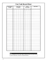
Page 34: ...m b e r 1 2000 U se r C ode 3 6 d ig its G ro u p A s s o c ia tio n U s e r N am e 1 2 3 4 Note For a complete list of user codes obtain a printout from either the remote printer Program Function 56...

Page 35: ...Up to 500 scheduled functions can be programmed Up to only 150 using AL DTM2 For Day Enter 1 Sunday 2 Monday 3 Tuesday 4 Wednesday 5 Thursday 6 Friday 7 Saturday 8 Monday through Friday 9 Saturday an...

Page 36: ...ly QUICK PC ACCESS CODE Permits upload download to DL Windows Software on IBM compatible 300 MHz or faster computer running Microsoft Windows 98 or NT 4 0 or higher Refers to the User Code for User 29...

Page 37: ...door without USER CODES door is unlocked PRINTER A printout device such as an infrared printer or computer printer PRIVACY A lock mode for privacy from other Users Time out Duration A maximum period o...

Page 38: ......

Page 39: ......

Page 40: ...are expressly canceled A LA R M LO C K neither assum es nor authorizes any other person purporting to act on its behalf to m odify to change or to assum e fo r it any othe r w arranty or liability co...

Reviews: