4.2 Wiring
4.2.1 Wire Routing
All wiring must be installed in accordance with NFPA70, NFPA72, and all local code requirements.
Power Limited wiring requires that power limited and non-power limited wiring remain physically
separated. Any power limited circuit entering the enclosure must remain at least one quarter inch
(
¼
”) away from any non-power limited circuit wiring. Any power limited circuit wiring must enter
and exit the enclosure through different knockouts than non-power limited circuit wiring. Wiring
within the enclosure should be routed around the perimeter of the cabinet. It should not be
routed across the circuit boards.
4.2.2 Control and Lock Power Inputs
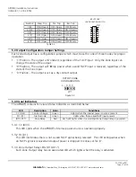
Locate the power input terminal block (TB7) and remove the terminal block from the header.
Connect one or both power inputs as appropriate for the settings of J1 and J2 (See Sections 3.3
and 5.1). Power input wiring should be sized appropriately for the total current draw from the
outputs of the APD8(F). See Section 3.3 for details. Replace the terminal block on the header.
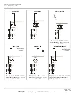
4.2.3 Zone Input Wiring
Locate the terminal block for the zone input to be wired and remove the terminal block from the
header. Connect the input in the manner appropriate for the type of input signal being applied.
See section 3.4 and Appendix A for more information. Replace the terminal block on the header.
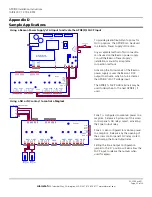
4.2.4 Zone Output Wiring
Locate the terminal block for the zone output to be wired and remove the terminal block from the
header. Connect the output in the manner appropriate for the application. See section 3.5 and
Appendix B for more information. Zone Output wiring should be sized appropriately for the total
current draw from the output. Replace the terminal block on the header.
4.2.5 FACP Input
Locate the FACP Input terminal block (TB8) and remove the terminal block from the header.
Connect the proper input in the manner appropriate for the type of input signal being applied.
See Section 3.6 and Appendix C for more information. Replace the terminal block on the header.
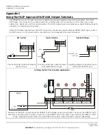
4.2.6 FACP AUX Output
Locate the FACP AUX Output terminal block (TB7) and remove the terminal block from the
header. Connect the FACP AUX Output as needed. See Section 3.7, Appendix C, and Appendix
D for more information. Replace the terminal block on the header.
APD8(F) Installation Instructions
10/9/2007, 12:19:29 PM
Page 13 of 24
AlarmSaf
65A Industrial Way, Wilmington, MA 01887 978 658 6717 www.alarmsaf.com
52-254 Rev B01

