Appendix A
Configuring The Zone Inputs For Any Application
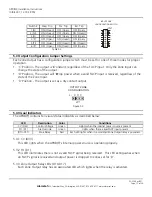
Each zone of the APD8(F) has a set of DIP switches associated with its input. These switches configure the input for use
with a variety of signal types, including:
y
Open Collector Input
y
Isolated Voltage Trip
y
Non-Isolated Positive Trip
y
Non-Isolated Negative Trip
y
Normally Closed Dry Contact - Negative Switching
y
Normally Open Dry Contact - Negative Switching
y
Normally Closed Dry Contact - Positive Switching
y
Normally Open Dry Contact - Positive Switching
Note -
Only switches one through 6 are used for each input - switches 7 & 8 are unused.
Off (Open)
Off (Open)
On (Closed)
Off (Open)
Off (Open)
On (Closed)
Off (Open)
On (Closed)
Switch 6
Off (Open)
On (Closed)
On (Closed)
Off (Open
Off (Open)
On (Closed)
Off (Open)
On (Closed)
Switch 5
Off (Open)
Off (Open)
On (Closed)
Off (Open)
Off (Open)
On (Closed)
Off (Open)
On (Closed)
Switch 4
On (Closed)
Off (Open)
Off (Open)
On (Closed)
On (Closed)
Off (Open)
On (Closed)
Off (Open)
Switch 3
On (Closed)
On (Closed)
Off (Open)
On (Closed)
On (Closed)
Off (Open)
On (Closed)
Off (Open)
Switch 2
On (Closed)
Off (Open)
Off (Open)
On (Closed)
On (Closed)
Off (Open)
On (Closed)
Off (Open)
Switch 1
Open
Collector
Input
Isolated
Voltage Trip
Non Isolated
Positive Trip
Non Isolated
Negative Trip
NC Dry
Contact
Negative
NC Dry
Contact
Positive
NO Dry
Contact
Negative
NO Dry
Contact
Positive
y
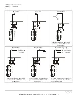
NO Dry Contact Positive
- This configuration will activate the zone’s output relay when the normally open contact
connected to the input closes. The NO contact is in series with the positive leg of the internal zone output relay coil.
y
NO Dry Contact Negative
- This configuration operates the same as the NO Dry Contact Positive configuration,
except that the NO contact is in series with the ground side of the internal zone output relay coil. This is the most
common configuration.
y
NC Dry Contact Positive
- This configuration holds the zone output relay active. The zone output relay deactivates
when the NC contact opens. The NC contact is in series with the positive leg of the internal zone output relay coil.
y
NC Dry Contact Negative
- This configuration operates the same as the NC Dry Contact Positive configuration,
except that the NC contact is in series with the ground side of the internal zone output relay coil.
y
Non-Isolated Negative Trip
- The positive source for the zone output relay coil is provided internally. A DC
common connected to the input’s ‘-’ terminal will activate the zone output relay. No connection is required to the
input’s ‘+’ terminal. The DC common used to activate the zone must be common grounded with the control power
input’s DC common.
y
Non-Isolated Positive Trip
- The DC common for the zone output relay coil is provided internally. A positive 12VDC
voltage connected to the input’s ‘+’ terminal will activate the zone output relay. No connection is required to the
input’s ‘-’ terminal. The positive voltage used to activate the zone must be common grounded with the control
power input’s DC common. Do not use a 24V source to activate the input or damage to the zone output relay will
occur.
y
Isolated Voltage Trip
- Connection of a 12VDC source across the input’s ‘+’ and ‘-’ terminals will activate the zone
output relay. When used in this mode, the zone input is completely isolated from the control power input and the
lock power input. Do not use a 24V source to activate the input or damage to the zone output relay will occur.
y
Open Collector Input
- This configuration is identical to the “NO Dry Contact Negative configuration, except that
the dry contact is replaced with the open collector output.
APD8(F) Installation Instructions
10/9/2007, 12:19:29 PM
Page 18 of 24
AlarmSaf
65A Industrial Way, Wilmington, MA 01887 978 658 6717 www.alarmsaf.com
52-254 Rev B01

