FEEDER ASSEMBLY
Locate unit
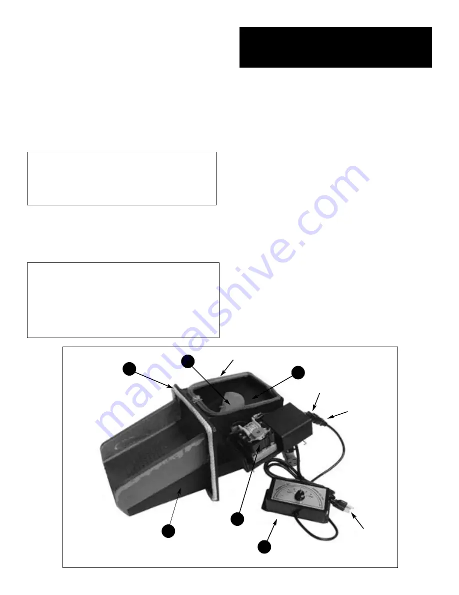
(See Fig. 1 on page 3 and Fig. 2 on page 2)
.
Check that strongback gasket is positioned properly as
shown in Fig 1. The strongback gasket position is critical
in that it prevents air escape to the hopper area which
could result in “hopper fire” or warpage to the overplate.
The cast iron grate should sit snug to the housing. The
gear motor moves the
feed bar
in a paddle like fashion,
to push the coal across the grate. A separate motor with a
plastic fan blows air through the grate for the combustion
process. Wiring should be connected as shown below.
NOTE:
Your feeder unit should come to you fully
assembled and ready to plug in.
RHEOSTAT
- is used to control the speed of your air
distribution fan and allows you the air push you desire.
NOTE:
Strongback is gray in color. make sure it’s
pinched between the grate and the feeder housing.
As shown below.
IMPORTANT:
Paddle should be
greased at least twice per year with standard grease
(see grease fitting position below)
. Grate gasket should
be applied to feeder housing.
WIRING:
Locate plug connections below, connect
the male and female plugs with matching letters
(example A.M. to A.F.)
connect C.M. to a 110 volt
wall outlet.
FEEDER ASSEMBLY
PARTS LIST
1. Auto Heat Control Box
2. Feeder Housing
3. Grate
4. Half Moon Feed Paddle
5. Plastic Wheel (Combustion Wheel)
6. Airmotor Tray
7. Cover Plate Bolt 1/4" x #20 x 2"
8. (4) #10/32 Nuts
9. Ball Joint Feed Arm
10. Feed Motor
11. Feed Motor Block
12. 1/2 Moon Feed Block
13. (2) 1/4" x #20 Wing Nuts
14. Strongback Gasket
15. Removable Feed Motor Tray
16. Airmotor / Combustion Motor
17. Grate Gasket 2' X Channel Gasket
18. Triple Plug Adapter
19. Paddle Plate (Note: 2 screws w/nut
3/8" x flat head not shown)
20. (2) 1/4" x #20 x 1" cap screws
21. Grease Fitting
22. 4' x 3/8" Rope Gasket
2
FIGURE 2
4
22
19
2
10
1
Hopper
Gasket
B.M.
B.F.
C.M.


