1. Components Overview
19
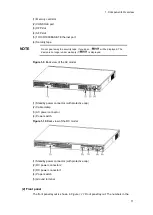
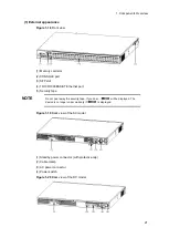
Figure 1-16
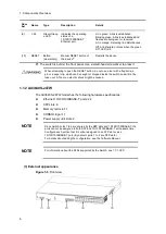
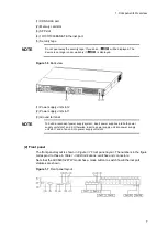
Back view
(1) Standby power connector (with protective cap)
(2) Cable clamp
(3) AC power connector
(4) Power switch
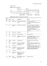
(2) Front panel
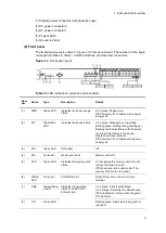
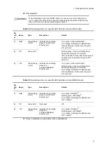
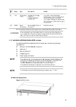
The front panel layout is shown in
Figure 1-17 Front panel layout
. The numbers in the
figure correspond to those in
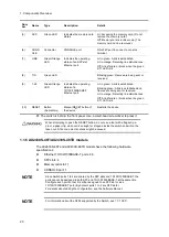
Table 1-12 LED indications, switches and connectors
Figure 1-17
Front panel layout
Table 1-12
LED indications, switches and connectors
Num
ber
Name
Type
Description
Details
(1)
PWR
Green LED
Indicates the power supply
status.
Lit in green: Powered-on.
Off: Powered-off or a failure with a power
supply unit.
(2)
ST1
Green/Red
LED
Indicates the device
status.
Lit in green: Standing by or operating.
Blinking green: Getting ready (starting up).
Blinking red: Partial failure with the switch
Lit in red: Fatal failure in the device
(operation cannot continue)
Off: Powered-off or a failure with a power
supply unit.
(3)
ST2
Green LED
(Not used)
Off
(4)
MC
Connector
Memory card slot
Memory card slot
Summary of Contents for AX2400S series
Page 3: ...Copyright Copyright C 2005 2011 ALAXALA Networks Corporation All rights reserved ...
Page 4: ......
Page 6: ...Preface II Find description from the AX2400S series manuals ...
Page 7: ...Preface III Find description from the AX3640S and AX3630S series manuals ...
Page 10: ...Preface VI ...
Page 14: ...Contents iv ...
Page 160: ...3 Preparation of Interface Cables and Terminals 130 ...

