ATS9462 User Manual
31
Analog Input
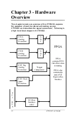
The two analog input channels are referenced to common
ground in bipolar mode. These settings are fixed; therefore,
neither the reference nor the polarity of input channels can be
changed. You cannot use CH A or CH B to make differential
measurements or measure floating signals unless you
subtract the digital waveforms in software.
For accurate measurements, make sure the signal being
measured is referenced to the same ground as your
ATS9462 by attaching the probe’s ground clip to the signal
ground.
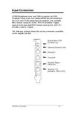
The EXTernal Trigger input (labeled TRIG IN) has a
programmable input range of ±5 V or ±1 V.
The CH A, CH B, and EXT inputs have a software-
programmable coupling selection between AC and DC. Use
AC coupling when your AC signal contains a large DC
component. Without AC coupling, it is difficult to view details
of the AC component with a large DC offset and a small AC
component, such as switching noise on a DC supply. If you
enable AC coupling, you remove the large DC offset for the
input amplifier and amplify only the AC component. This
technique makes effective use of dynamic range to digitize
the signal of interest.
The
low-frequency corner
in an AC-coupled circuit is the
frequency below which signals are attenuated by at least 3
dB. The low-frequency corner is approximately 10 Hz with 1
M
Ω
input impedance and 100 KHz with 50
Ω
input
impedance.

