Albalá Ingenieros | Manual
DVM3001C02
3. INSTALLATION
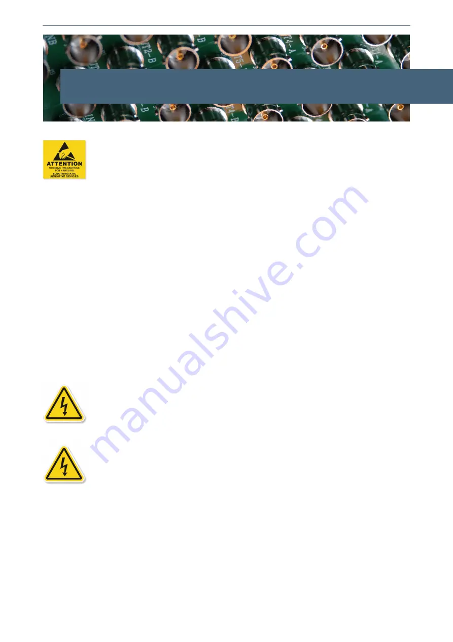
THE DVM3001C02 MODULE CONTAINS ELECTRONIC DEVICES SENSITIVE TO
ELECTROSTATIC DISCHARGE. Always use antistatic bags clearly identified
with a high degree of shielding for storage and transportation.
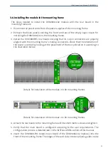
The DVM3001C02 module is composed of two parts: one DVM3001P01 main board and
one XVD3000P05 rear board. Both parts must be installed in a UR3000 or UR3100
mounting frame following the instructions in the corresponding section of this chapter.
3.1. Initial inspection
Verify that the package has been properly handled during transport. After opening the
packaging, check that one DVM3001P01 main board and one XVD3000P05 rear board
are inside.
You must notify your Albalá Ingenieros distributor or dealer of any damage or defects
observed.
Follow the instructions in this manual to install this module in the mounting frame.
3.2. Safety instructions
• This equipment must be connected to a mains outlet with a protective
earth connection. Never use extension cords that do not have protective
earthing connection. The lack of an effective electrical connection between
the ground pin in the mains input connector of the equipment and the
protective earth of the electrical power distribution can cause serious harm.
• All modules of the Albalá Ingenieros TL3000 terminal line can be
hot-plugged or unplugged without suffering any damage or affecting the
processes that are currently taking place in other modules in the same
mounting frame. When a module is installed in an empty bay of a mounting
frame, it is necessary to mount the rear board that is part of that module.
Prior to installing this board, the mounting frame must be disconnected
from the power supply network.
This is required because in addition to the
risk of electrocution for the person handling the device it is possible that a
high instantaneous current coming from the power supply could damage
the connectors and components of the mounting frame and/or the rear
board.
11
Summary of Contents for DVM3001C02
Page 2: ...DVM3001C02 ...
Page 4: ...DVM3001C02 ...
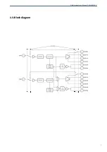
Page 7: ...Albalá Ingenieros Manual DVM3001C02 1 3 Block diagram 7 ...
Page 8: ...Albalá Ingenieros Manual DVM3001C02 DVM3001C02 8 ...
Page 16: ...Albalá Ingenieros Manual DVM3001C02 DVM3001C02 16 ...
Page 24: ...Albalá Ingenieros Manual DVM3001C02 DVM3001C02 24 ...
Page 26: ...Albalá Ingenieros Manual DVM3001C02 DVM3001C02 26 ...


