background image

Albalá Ingenieros | Manual 

FRS3004C02

3.6. Installing the module in the mounting frame

The steps needed to install the FRS3004C02 module with the rear board in the mounting
frame are:

1 - Disconnect all power cords from the power supplies of the mounting frame.

2 - Remove the blank panels covering the front and rear of the empty bays chosen for

installing the FRS3004C02 in the mounting frame.

3 - Install the FRS3004P02 rear board ensuring that its 12-pin connectors are properly

aligned with the mounting frame´s mating connectors. Check that the orientation of
the board is correct by looking at the placement of the text printed on it according to
the illustration below.

 Details for installation of the module in 3 RU mounting frames

 Details for installation of the module in 1 RU mounting frames

4 - Attach the rear board to the mounting frame with two M3 metric screws and tighten.

5 - Verify that the main board is configured according to the user requirements. The

configuration process is detailed later in the INSTALLATION section of this manual.

6 - Insert the FRS3004P01 board (main board of the FRS3004C02 module) into the front

of the mounting frame. The edges of the card slide into two plastic guides inside the

13

Summary of Contents for FRS3004C02

Page 1: ...FRS3004C02 QUAD SD SDI DIGITAL VIDEO FRAME SYNCHRONIZER WITH BYPASS RELAYS Version 1 0 Albalá Ingenieros S A Medea 4 28037 Madrid Spain 23 January 2017 Albalá Ingenieros S A All rights reserved ...

Page 2: ...FRS3004C02 ...

Page 3: ...tions 12 3 4 Power considerations 12 3 5 Module configuration 12 3 6 Installing the module in the mounting frame 13 3 7 Interconnection 14 3 7 1 Electrical SDI video connections 15 3 7 2 Electrical analog video connections 15 4 OPERATION 17 4 1 Front panel description 17 4 2 Configuration from the front panel 19 4 3 Functional description 19 4 4 Module remote control and supervision 21 4 4 1 Detai...

Page 4: ...FRS3004C02 ...

Page 5: ...ed in the frame memory Each section includes a bypass relay on the rear board that connects the input signal to one of the output connectors if the power supply fails or the main board of the module is extracted from its mounting frame It is possible to monitor the FRS3004C02 status remotely using a communications controller module installed in the same mounting frame In addition certain controlle...

Page 6: ...signal or to freeze the last correct frame when the input signal is lost Vertical and horizontal delay adjustment for each section Luminance chrominance and black levels adjustable for each section Performs complete EDH packet processing 10 bit internal SDI signal processing Module control and supervision can be done remotely when the mounting frame is equipped with a communications controller mod...

Page 7: ...Albalá Ingenieros Manual FRS3004C02 1 3 Block diagram 7 ...

Page 8: ...Albalá Ingenieros Manual FRS3004C02 FRS3004C02 8 ...

Page 9: ...o output bypass insertion loss 0 1 dB up to 270 MHz Number of outputs 2 per section Amplitude 800 mVpp 10 Rise and fall time 20 80 1 ns typ SD SDI digital video signal Signal format According to SMPTE ST 259 standard Bit rate 270 Mbit s Black burst reference signal input Connector BNC Return loss 40 dB at fsc Type Passive Loop Through Signal format According to ITU R BT 470 6 standard Accepted for...

Page 10: ...Albalá Ingenieros Manual FRS3004C02 Approximate weight 350 g 10 ...

Page 11: ...ns This equipment must be connected to a mains outlet with a protective earth connection Never use extension cords that do not have protective earthing connection The lack of an effective electrical connection between the ground pin in the mains input connector of the equipment and the protective earth of the electrical power distribution can cause serious harm All modules of the Albalá Ingenieros...

Page 12: ...ured before installing the module into mounting frame This configuration can be modified using the control software however upon startup the values set by the microswitches take precedence Switch S1 configures the operating mode of the module as shown in the following table S1 OFF ON 1 REF DGTL ANLG 2 FAIL BLK FRZ 3 SYNC LIN FRM REF Specifies which type of reference signal the module will use anal...

Page 13: ...s mating connectors Check that the orientation of the board is correct by looking at the placement of the text printed on it according to the illustration below Details for installation of the module in 3 RU mounting frames Details for installation of the module in 1 RU mounting frames 4 Attach the rear board to the mounting frame with two M3 metric screws and tighten 5 Verify that the main board ...

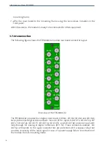
Page 14: ...2 The FRS3004C02 provides four digital video inputs SDI IN1 SDI IN2 SDI IN3 and SDI IN4 two synchronized digital video outputs for each of the inputs SDI OUT1 SDI OUT1p SDI OUT2 SDI OUT2p SDI OUT3 SDI OUT3p SDI OUT4 and SDI OUT4p and one input with loop through for analog or digital references REF IN Those connectors labeled SDI OUTXp correspond to the signal outputs that are protected with a bypa...

Page 15: ...al cable used must be Belden 8281 or similar This type provides the greatest lengths because it is used to calculate the equalizers in the FRS3004C02 Cables carrying signal between the module and the devices should use single piece construction avoiding spliced sections with double BNC female or barrel connectors If it is necessary to split the cable into two sections the same type of wire should ...

Page 16: ...Albalá Ingenieros Manual FRS3004C02 FRS3004C02 16 ...

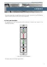
Page 17: ...ont panel indicators of the FRS3004C02 module and their remote control and monitoring ability 4 1 Front panel description The appearance of the front panel and the elements it contains are shown in the following illustration Front panel of the FRS3004C02 The panel contains the following elements 17 ...

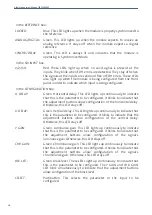
Page 18: ...nt buttons allow configuration of the horizontal delay Otherwise this LED stays off V DELAY Green Vertical delay This LED lights up continuously to indicate that this is the parameter to be configured It blinks to indicate that the adjustment buttons allow configuration of the vertical delay Otherwise this LED stays off Y GAIN Green Luminance gain This LED lights up continuously to indicate that t...

Page 19: ...figured value A short press causes a single unit change of the parameter whereas a sustained press longer than one second will cause coarse changes The ZERO LED indicates that the selected value corresponds to the default from calibration no delay gains of 1 for luminance and chrominance no offset in the black level A sustained press of the SELECT button validates the value of the parameter at tha...

Page 20: ...Mode the vertical sync information must be recovered before the system begins to write data to the frame memory again Line Synchronizer Mode is used for recovery of SDI signals with defective bits for example as a result of a switching event Frame Synchronizer Mode has been designed for exclusive use with video signals coming in from outside the production environment The user can configure the de...

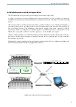
Page 21: ...ion The FRS3004C02 can optionally be remotely controlled supervised In order to perform remote configuration and supervision of the module an optional TL3000 family remote communications controller must be installed in the mounting frame The main function of the communications control module is to interface between a 10 100 Ethernet port an EIA RS232 or an EIA RS485 serial port and the internal bu...

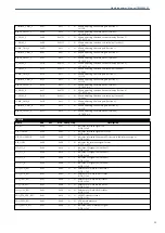
Page 22: ...ital FAIL_MODE 0x00 0x02 Y N Allows selecting the output video signal if the input fails 0 Freeze 1 Black SYNCHRO_MODE 0x00 0x04 Y N Allows selecting the synchronizing mode 0 Frame 1 Line VBI_MODE 0x00 0x08 Y N Allows selecting if the VBI is blanked 0 Pass 1 Blank NO_REF_MASK 0x01 0x01 N N Allows masking no reference signal fail 0 Disabled 1 Enabled REF_UNLOCK_MASK 0x01 0x02 N N Allows masking ref...

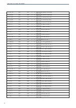
Page 23: ... adjusting the luma gain Section 4 x 128 CHROMA_GAIN_4 0x1C 0xFF Y N Allows adjusting the chorma gain Section 4 x 128 BLACK_OFFSET_4 0x1D 0xFF Y N Allows adjusting the black offset Section 4 0 781 x mV STATUS Name add ext msk snmp trap Description NO_REF 0x00 0x01 Y Y Indicates reference signal fail 0 OK 1 Fail REF_UNLOCK 0x00 0x02 Y Y Indicates reference signal unlock fail 0 OK 1 Fail REF_EDH_ERR...

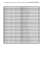
Page 24: ... 1 0 OK 1 Fail ACT_IDA_1 0x04 0x08 N N Active picture IDA bit status Section 1 0 OK 1 Fail ACT_UES_1 0x04 0x10 N N Active picture UES bit status Section 1 0 OK 1 Fail FULL_EDH_2 0x05 0x01 N N Full field EDH bit status Section 2 0 OK 1 Fail FULL_EDA_2 0x05 0x02 N N Full field EDA bit status Section 2 0 OK 1 Fail FULL_IDH_2 0x05 0x04 N N Full field IDH bit status Section 2 0 OK 1 Fail FULL_IDA_2 0x0...

Page 25: ...atus Section 4 0 OK 1 Fail FULL_IDA_4 0x09 0x08 N N Full field IDA bit status Section 4 0 OK 1 Fail FULL_UES_4 0x09 0x10 N N Full field UES bit status Section 4 0 OK 1 Fail EDH_PCK_ERR_4 0x09 0x20 N N Valid EDH packet status Section 4 0 OK 1 Fail EDH_PRES_4 0x09 0x40 N N EDH packet presence Section 4 0 No 1 Yes EDH_ERROR_4 0x09 0x80 Y N Indicates error in SDI signal Section 4 0 OK 1 Fail ACT_EDH_4...

Page 26: ...Albalá Ingenieros Manual FRS3004C02 FRS3004C02 26 ...

Page 27: ...alculates the CRC for the data received and compares it with the CRC received in the packet to determine if errors are present in the transmission SD SDI Standard Definition Serial Digital Interface A serial digital interface capable of transmitting standard definition television signals with bitrates of 143 Mbit s 177 Mbit s 270 Mbit s or 360 Mbit s SDI Serial Digital Interface A standard used fo...

Page 28: ...Albalá Ingenieros Manual FRS3004C02 FRS3004C02 28 ...

Page 29: ...onal analogue television systems See also ITU R BT 1700 SMPTE 170M SMPTE RP 165 1994 Error Detection Checkwords and Status Flags for Use in Bit Serial Digital Interfaces for Television SMPTE ST 259 2008 SDTV Digital Signal Data Serial Digital Interface See also ITU R BT 656 5 29 ...

Page 30: ...Albalá Ingenieros Manual FRS3004C02 FRS3004C02 30 ...

Page 31: ...Albalá Ingenieros Manual FRS3004C02 7 VERSIONS Ver Date Description 0 0 13 06 2013 Preliminary Version 1 0 23 01 2017 First version ...

Page 32: ...Albalá Ingenieros S A Medea 4 28037 Madrid Spain 34 913274453 www albalaing com info albalaing com ...

Reviews: