Albalá Ingenieros | Manual
TTD2000C01
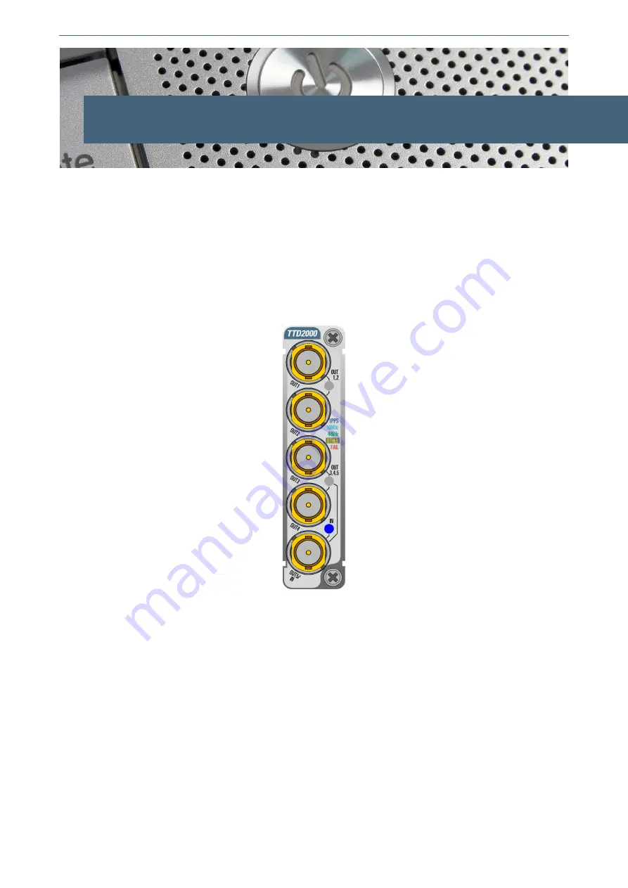
4. OPERATION
This section describes the significance of the front panel indicators of the TTD2000C01
module and their remote control and monitoring ability.
4.1. Front panel description
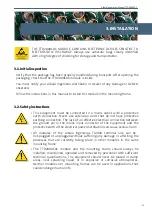
The appearance of the front panel and the elements it contains are shown in the
following illustration.
Front panel of the TTD2000C01
In addition to the connectors previously described in the Interconnection section the
front panel includes the following indicators and controls:
IN:
The LED lights up only when the TTD2000C01 acts as a distributor and
indicates the type of signal detected at the input.
1PPS. Blue, blinking. Indicates that a 1 PPS signal has been detected.
10MHz.Cyan. Indicates that a signal has been detected at the input but the
levels are not TTL compatible. Normally this is a 10MHz reference signal.
48kHz. Green. Indicates that a TTL signal at 48kHz has been detected.
OTHER. Yellow. Indicates that a TTL signal with a frequency other than
48kHz has been detected.
FAIL. Red. Indicates that no signal has been detected at the input.
15
Summary of Contents for TTD2000C01
Page 2: ...TTD2000C01 ...
Page 4: ...TTD2000C01 ...
Page 7: ...Albalá Ingenieros Manual TTD2000C01 1 3 Block diagram 7 ...
Page 8: ...Albalá Ingenieros Manual TTD2000C01 TTD2000C01 8 ...
Page 10: ...Albalá Ingenieros Manual TTD2000C01 TTD2000C01 10 ...
Page 14: ...Albalá Ingenieros Manual TTD2000C01 TTD2000C01 14 ...
Page 22: ...Albalá Ingenieros Manual TTD2000C01 TTD2000C01 22 ...
Page 23: ...Albalá Ingenieros Manual TTD2000C01 6 REGULATIONS 23 ...
Page 24: ...Albalá Ingenieros Manual TTD2000C01 TTD2000C01 24 ...


