15
Nov. 2006
ELECTRICAL INSTALLATION
The following instructions are recommended guidelines for electrically installing a typical Model 355
door. Actual wiring may be different based on what options, special instructions, special components,
etc. were ordered with the door. Consult the electrical schematics that are supplied with the door. These
should be located inside the control panel.
WARNING
CONTROL PANEL CONTAINS HIGH VOLTAGE. THE FOLLOWING
PROCEDURES SHOULD BE PERFORMED BY QUALIFIED ELECTRICAL
PERSONNEL ONLY. WIRING MUST MEET ALL LOCAL, STATE, FEDERAL,
INTERNATIONAL, OR OTHER GOVERNMENT AGENCY CODES. FAILURE TO
DO COULD RESULT IN SERIOUS INJURY OR DEATH.
NOTE
TO AID THE WIRING AND SERVICE OF ALL ELECTRICAL CIRCUITS, TAG OR
LABEL ALL WIRE ENDS DURING THE FOLLOWING ELECTRICAL INSTALLATION.
ALSO, ALL THREE PHASE POWER WIRES SHOULD BE RUN IN SEPARATE
CONDUIT FROM ALL OTHER CONTROL CIRCUIT WIRING (I.E. PULSE ENOCDER
WIRING).
1.
Mount the control panel at a height of approximately four feet from the floor on the drive side of the
door.
2.
Run electrical conduit and wires for: pulse encoder cable, drive unit power leads, and receptacle
cable. Plug all wires into the electrical receptacles located above the drive unit (Figure 11).
3.
Install all the actuators and wire according to the electrical schematics supplied with the door.
4.
Install a fused disconnect beside the control panel. The main supply to the All
★
Star drive system
can be from 208 VAC up to 600 VAC. The control panel is fused at 15 amps.
CAUTION
VERIFY ALL FIELD WIRING TO ENSURE TERMINAL CONNECTIONS ARE
TIGHT AND CORRECT. A FUSED DISCONNECT IS REQUIRED FOR EACH
ALBANY DOOR AS A MEANS OF DISCONNECTING INCOMING POWER FROM
THE CONTROL PANEL.THIS DISCONNECT IS NORMALLY SUPPLIED BY
OTHERS.
Summary of Contents for 350016-0000
Page 3: ......
Page 12: ...12 Nov 2006 Figure 6 Figure 7 ...
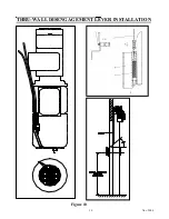
Page 14: ...14 Nov 2006 THRU WALL DISENGAGEMENT LEVER INSTALLATION Figure 10 ...
Page 20: ...20 Nov 2006 ...


