Part # 6410T0008
Rev.F
-12-
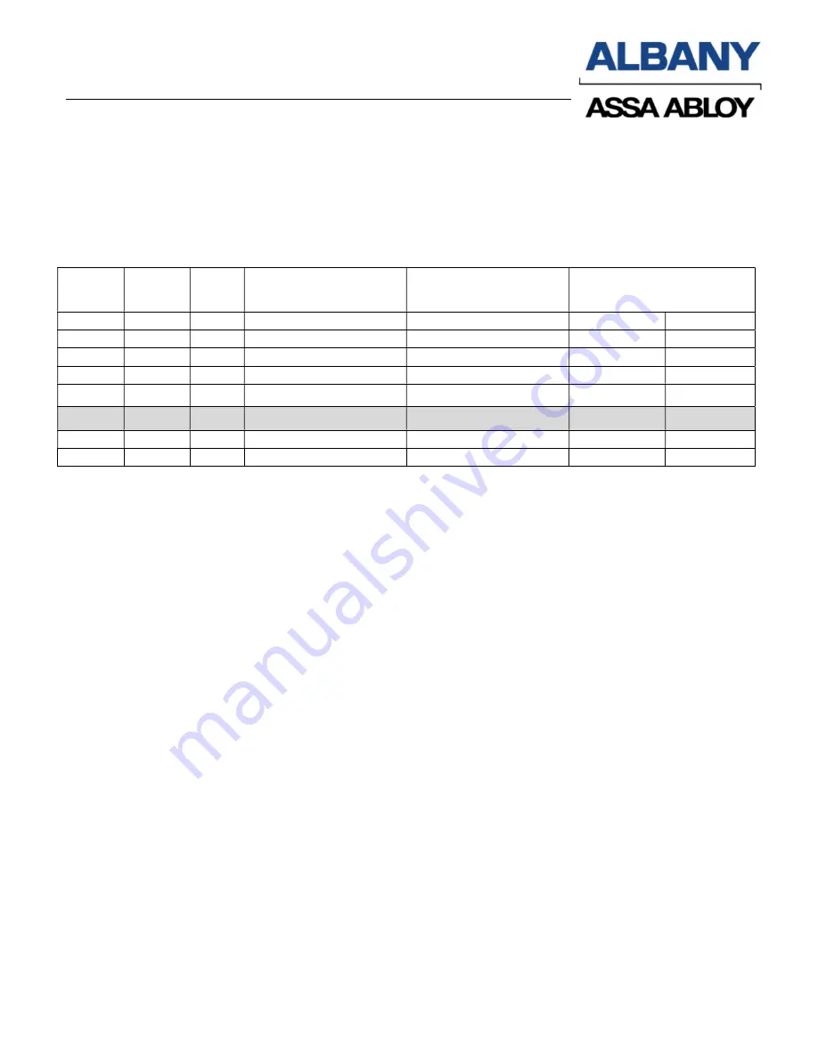
Setting of Opening and Closing Functions
In the table below,
SW1.1
means switch position 1 on
SW1
dipswitch. Likewise,
SW1.2
means
switch position 2 on
SW1
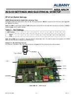
dipswitch. Refer to
Figure 12
for switch location. The greyed out section
below shows the factory settings. You need to change these settings for your particular needs.
Table 3– Setting of Opening and Closing Functions
SW 1.1 SW 1.2 SW 2
Terminal 3(A),4(A)
(Remote Activation)
Terminal 5(A),6(A)
(Remote Activation)
Panel Buttons
UP DOWN
ON
ON
0
UP – DOWN
UP – DOWN
UP
DOWN
ON
ON
1-F
UP – AUTO. + CAP
UP – DOWN
UP- AUTO
DOWN
ON
OFF
0
UP
UP – DOWN
UP
DOWN
ON
OFF
1-F
UP – AUTO.
UP – DOWN
UP - AUTO
DOWN
OFF
ON
0
UP + CAP
DOWN
UP - CAP
DOWN
OFF
ON
1-F
UP – AUTO.
UP – AUTO.
UP - AUTO
DOWN
OFF
OFF
0
UP
DOWN
UP
DOWN
OFF
OFF
1-F
UP – AUTO.
DOWN
UP - AUTO
DOWN
SW1.3
OFF
= Does not require reset after safety edge trip.
ON
= Requires reset after safety edge trip. Must reset by hold to close by pressing down
button and fully closing the door
LEGEND for Table 3:
AUTO.
= Automatic closing from open position. Delay before close time is adjustable from1 sec to
60 seconds depending on SW2 setting as specified in
TABLE 2
. The UP button (or 3(A) & 4(A)
remote) will reset the timer, and prevent the door from closing until released. The shaded row in the
above table is the most commonly used settings for auto close function.
CAP
= Automatic
“CLOSE AFTER PASSING”
the door photocell. The door will remain open until
the photocell beam is broken and re-established. If the door is in UP – AUTO + CAP mode, it will
then close after a fixed 2-second delay (not adjustable) once the photos have been passed through
and cleared. If the door is in UP –CAP mode, the door will then close after the UP (or 3(A) & 4(A)
remote) or DOWN (or 5(A) & 6(A) remote) buttons are pressed
UP – DOWN
= When the door is open, an impulse of the UP button (or 3(A) & 4(A) remote) will
close the door when in this mode.
Summary of Contents for ACS-50
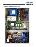
Page 5: ...Part 6410T0008 Rev F 5 ACS50 Control Panel Interior Single speed ...
Page 7: ...Part 6410T0008 Rev F 7 Figure 7 Single Speed Motherboard ...
Page 8: ...Part 6410T0008 Rev F 8 Figure 8 Two Speed Motherboard ...
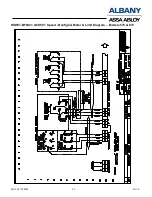
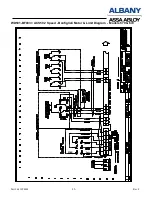
Page 34: ...Part 6410T0008 Rev F 34 ACS50 Contactless Safety Edge Wiring if equipped ...
Page 35: ...Part 6410T0008 Rev F 35 Blanking Light Curtain Photocell Wiring ...
Page 36: ...Part 6410T0008 Rev F 36 ACS 50 Floor Loop 2Posi Selector Switch ...

