background image


Part # 6410T0008                


Rev.F 

-27-


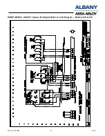
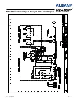
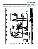
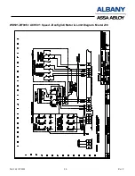
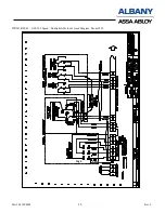
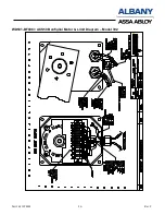
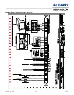
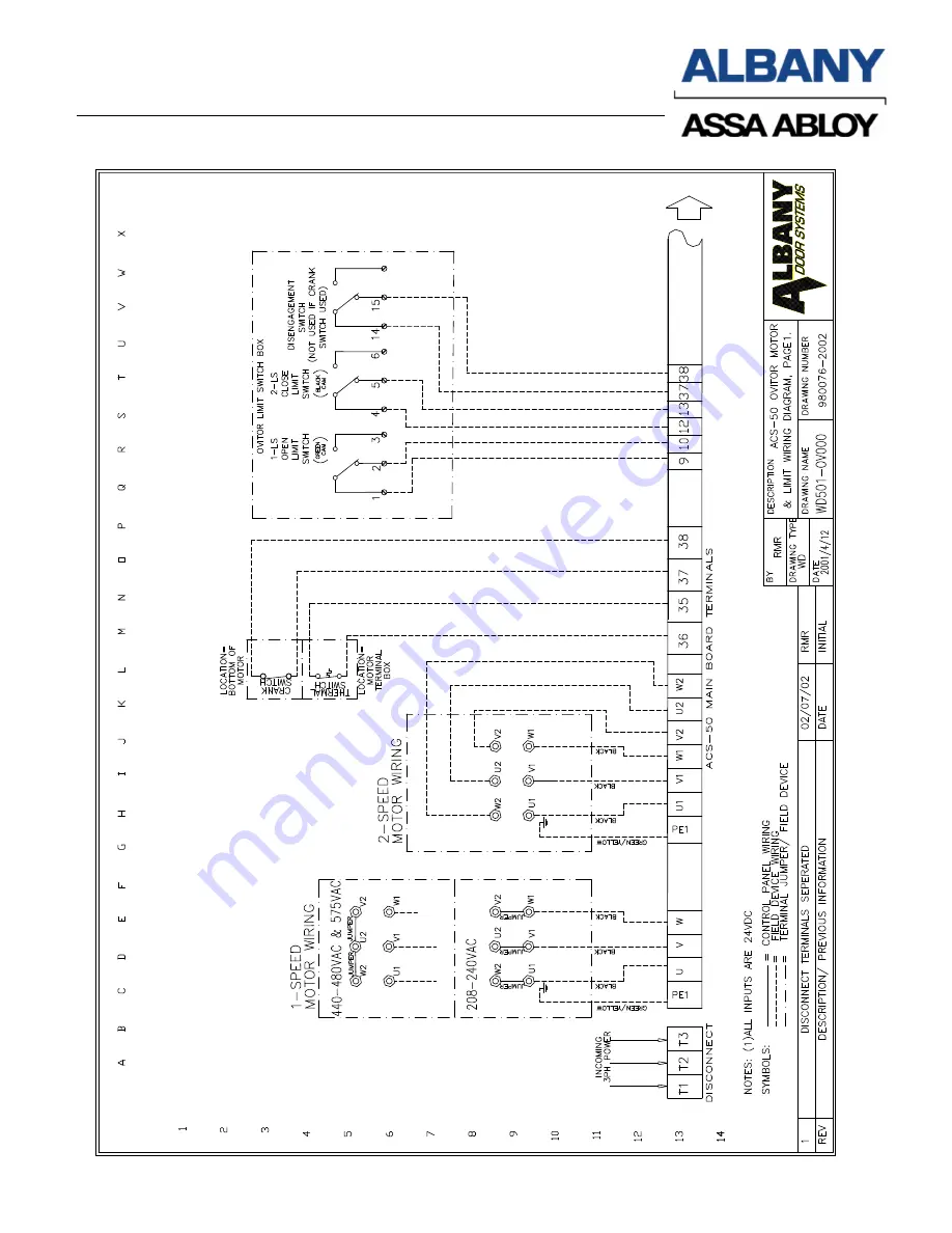
WD501-0V000 = ACS50 Ovitor Motor & Limit Diagram 


co

m

pa

ny

 o

Al

ba

ny

 ln

te

rn

at

io

na

l C

or

p.


Summary of Contents for ACS-50

Page 1: ...6410T0008_REV_G USER MANUAL ACS 50 CONTROL PANEL ASSA ABLOY ENTRANCE SYSTEMS 975 A Old Norcross Road Lawrenceville Ga 30046 800 252 2691 Tel 770 338 5034 Fax www albanydoors com ...

Page 2: ...t off GFA Drives Only 17 Inertia Brake Wiring if Equipped 17 Pressure Switch Adjustment if Equipped 18 TROUBLESHOOTING 19 WD501 BF002 ACS50 1 Speed Bonfiglioi Motor Limit Diagram Models 570 670 21 WD501 BF003 ACS50 2 Speed Bonfiglioli Motor Limit Diagram Models 570 670 22 WD501 BF007 ACS50 1 Speed Bonfiglioli Motor Limit Diagram Model 392 23 WD501 BF006 ACS50 1 Speed Bonfiglioli Motor Limit Diagra...

Page 3: ...IMENSIONS 11 8 W X 15 75 H X 8 25 DEEP WEIGHT 24 LBS ALBANY DOOR SYSTEMS RAPID ROLL DRIVE UNITS 1 speed brake motor 2 speed brake motor Unit Output power 1 5 1 5 1 HP Voltage 208 240 440 480 550 600 208 240 440 480 550 600 VAC Current 4 9 2 5 1 85 4 9 3 6 2 5 1 8 1 87 1 36 A NEMA 12 13 12 13 Protection Thermal Switch Thermal Switch WARNING DO NOT INSTALL OPERATE OR SERVICE THIS PRODUCT UNLESS YOU ...

Page 4: ... MINIMUM OF 18 AWG 1 NOTE REFERENCE FIGURE BELOW AS A GUIDE FOR MAKING THESE WIRE CONNECTIONS TO THE UNIQUE WAGO STYLE TERMINALS WARNING A SEPERATE FUSED DISCONNECT IS REQUIRED FOR PROTECTION OF THE DRIVE AND CONTROL SYSTEM THIS DISCONNECT IS TO BE SUPPLIED BY OTHERS THE DISCONNECT PROVIDED ON THE CONTROL BOX IS NON FUSED ALL CONDUIT PENATRATIONS MUST BE IN THE BOTTOM OF THE CONTROL PANEL ENCLOSUR...

Page 5: ...Part 6410T0008 Rev F 5 ACS50 Control Panel Interior Single speed ...

Page 6: ...he motherboard inside the ACS 50 control box ACS50 Control Panel Interior Two speed Contactor KM1 and KM2 Control Fuses FU1 FU6 Cycle Counter CPU Card Slot Brake Rectifier 230VAC Panel Disconnect Non fused Voltage Selector Jumper J2 Motherboard Contactor KM3 2 Speed Only Motor lead wiring ...

Page 7: ...Part 6410T0008 Rev F 7 Figure 7 Single Speed Motherboard ...

Page 8: ...Part 6410T0008 Rev F 8 Figure 8 Two Speed Motherboard ...

Page 9: ... control panel but located on the end of the safety edge Electric Edge Connection if equipped Connect the electric edge directly to terminals 7 and 8 edge is not adjustable To test turn power on bump the rubber safety edge with your hand observe LED 6 see Figure 5 for location it should flash on briefly The edge is now operational Ground Bar All grounds coming into the panel should be terminated o...

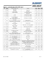
Page 10: ...22A Safety photocell 2 power DC 23A Safety photocell 2 Signal 33 Output 24VDC Negative 33A 34 Output 24VDC Positive 34A 35 36 Motor Thermal switch contact jumper to 36 if not used 37 38 Hoist or Brake disengagement jumper to 38 if not used 45 46 Optional Crash sensor jumper to 46 if not used 53 54 Reserve input 55 56 Reserve output 63 64 Output 24V AC 70 71 BRAKE 180VDC output not used on Ovitor m...

Page 11: ...as shown in Table 4 Refer to Figure 12 for switch location Table 2 Sw2 Settings SW2 Position 0 1 2 3 4 5 6 7 8 9 A B C D E F Close Time 1 2 3 4 5 7 10 13 16 19 22 25 30 45 60 Note When SW2 is set in position 0 the door will not automatically close You need to give a new impulse of an OPEN device to close the door or impulse a CLOSE device Jumper J1 Bottom Edge Selector The Jumper1 is located on th...

Page 12: ...y edge trip ON Requires reset after safety edge trip Must reset by hold to close by pressing down button and fully closing the door LEGEND for Table 3 AUTO Automatic closing from open position Delay before close time is adjustable from1 sec to 60 seconds depending on SW2 setting as specified in TABLE 2 The UP button or 3 A 4 A remote will reset the timer and prevent the door from closing until rel...

Page 13: ...door is closing Test of close relay OFF OFF OFF 14 Yellow Ribbon Cable Close button of the control box OFF OFF OFF 15 Green 20A 21A 22A 23A Jump 21A 23A to bypass for testing only See schematics for color code wiring Safety photocell 2 Off if beam is blocked or not aligned ON ON ON 16 Yellow Not Used OFF OFF OFF 17 Yellow Tab on open contactor will move when door is opening Relay Open OFF OFF OFF ...

Page 14: ...is Figure 14 is the STROMAG limits box Figure 15 is the TEMEC limit box Figure 16 is the GFA limit Box Figure 14 Figure 15 Adjustment Screw Closed Limit Cam Open Limit Cam Microswitches Microswitches Top Limit Bottom Limit Allen Wrench Figure 17 Contact point Micro switch Adjustment point Cam Lock Gearbox Close Limit Cam Open Limit Cam Figure 16 ...

Page 15: ... this safety point needs to be corrected this can be adjusted using the fine adjustment screw to advance or retard the position of the red cam in relation to the position of the green cam The red cams are so the door stops safely if the direction of the rotation is reversed or the open limit switch fails During normal operation the RED cams should never make contact with their switch but should be...

Page 16: ...s necessary to push the Close button to reset the door controller Every other signal to reset will not have any effect Reset of the Hold to run mode will occur when both safety circuits are working again and pushing the CLOSE button on the control panel successfully closes the door Input Device Check Press the STOP button to prevent the door from moving Operate each applicable input device as list...

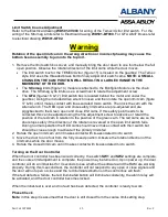
Page 17: ...on the limit switch figure 18 are reserved for the safety circuit An interruption of the safety circuit causes the control voltage to be interrupted Electrical operation is no longer possible when this occurs Photocell Cut off GFA Drives Only The limit switch S6 must be adjusted to bypass the photocells when the door is approximately 8 inches off the ground This allows the bottom loop on the botto...

Page 18: ...Figure 19 Remove the cover of the pressure switch enclosure Rotate the white plastic screw on the pressure switch clockwise with a small screwdriver until the LED 6 turns on Then rotate the screw counter clockwise until LED 6 turns off and then rotate an additional turn Test the safety edge and observe LED 6 it should turn on momentarily whenever pressure is applied to safety edge Note LED 26 turn...

Page 19: ... is locked ON ON Safety edge was triggered SW1 3 ON LED 26 ON ON ON EPROM Check sum error Door controller is locked No power on test indication ON ON RAM Error Door controller is locked No power on test indication If LED s 7 8 9 or 15 is not on when the system is powered up it will go into a locked condition Reset power and see which light is not lit and then check that item to get that light to b...

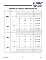
Page 20: ...9 9 208V 3 Phase 3 0 10 6 13 0 208V 3 Phase 230V 1 SPEED 2 0 6 3 7 8 230V 3 Phase 3 0 9 6 10 7 230V 3 Phase 2 SPEED 2 0 6 3 7 8 230V 3 Phase 3 0 9 6 10 7 230V 3 Phase 460V 1 SPEED 2 0 3 4 3 9 460V 3 Phase 3 0 4 8 5 47 460V 3 Phase 2 SPEED 2 0 3 4 3 9 460V 3 Phase 3 0 4 8 5 47 460V 3 Phase 575V 1 SPEED 2 0 9 6 10 7 575V 3 Phase 3 0 3 9 4 3 575V 3 Phase 2 SPEED 2 0 9 6 10 7 575V 3 Phase 3 0 3 9 4 3 ...

Page 21: ...Part 6410T0008 Rev F 21 WD501 BF002 ACS50 1 Speed Bonfiglioi Motor Limit Diagram Models 570 670 A company of Albany lnternational Corp ...

Page 22: ...Part 6410T0008 Rev F 22 WD501 BF003 ACS50 2 Speed Bonfiglioli Motor Limit Diagram Models 570 670 A company of Albany lnternational Corp High Low ...

Page 23: ...Part 6410T0008 Rev F 23 WD501 BF007 ACS50 1 Speed Bonfiglioli Motor Limit Diagram Model 392 A company of Albany lnternational Corp ...

Page 24: ...Part 6410T0008 Rev F 24 WD501 BF006 ACS50 1 Speed Bonfiglioli Motor Limit Diagram Model 230 A company of Albany lnternational Corp ...

Page 25: ...Part 6410T0008 Rev F 25 WD501 BF005 ACS50 2 Speed Bonfiglioli Motor Limit Diagram Model 230 A company of Albany lnternational Corp High Low ...

Page 26: ...Part 6410T0008 Rev F 26 WD501 BF008 ACS50 Bonfiglioi Motor Limit Diagram Model 392 A company of Albany lnternational Corp ...

Page 27: ...Part 6410T0008 Rev F 27 WD501 0V000 ACS50 Ovitor Motor Limit Diagram A company of Albany lnternational Corp ...

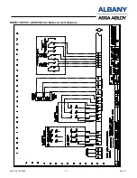
Page 28: ...Part 6410T0008 Rev F 28 WD501 GF002 ACS50 GFA Operator Wiring 1 Speed A company of Albany lnternational Corp ...

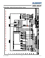
Page 29: ...Part 6410T0008 Rev F 29 WD501 GF001 ACS50 GFA Operator Wiring 2 Speed A company of Albany lnternational Corp High Low ...

Page 30: ...Part 6410T0008 Rev F 30 WD502 0000 1 Door Control Wiring Electric Edge and Crash Sensor A company of Albany lnternational Corp ...

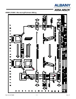
Page 31: ...Part 6410T0008 Rev F 31 WD503 PC000 Reversing Photocell Wiring A company of Albany lnternational Corp ...

Page 32: ...Part 6410T0008 Rev F 32 WD504 0000 ACS50 Actuator Options A company of Albany lnternational Corp ...

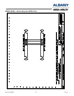
Page 33: ...Part 6410T0008 Rev F 33 WD502 0000A Interlocking two ACS50 Units A company of Albany lnternational Corp ...

Page 34: ...Part 6410T0008 Rev F 34 ACS50 Contactless Safety Edge Wiring if equipped ...

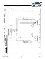
Page 35: ...Part 6410T0008 Rev F 35 Blanking Light Curtain Photocell Wiring ...

Page 36: ...Part 6410T0008 Rev F 36 ACS 50 Floor Loop 2Posi Selector Switch ...

Page 37: ...1T0013 Terminal Block End Stop 35mm Din Rail 4920T0001 Motherboard ACS50 CUL One Speed Does not include CPU card or rectifier 4920T0002 Motherboard ACS50 CUL Two Speed Does not include CPU card or rectifier 4920T0009 CPU CARD ACS50 w 4916T0002 40 Sec Run Time Eprom 980072 4019 Resistor 8 2K 1 8w Pigtail for Pnuematic edge 980072 7504 Disconnect Rotary Switch Rod And Handle Included 980072 9500 FUS...

Page 38: ...008 Rev F 38 NOTES DOCUMENT TITLE ACS 50 Control Panel Manual DOCUMENT NUMBER 980076 0000 ISSUE DATE September 2009 DOOR MODEL S ALL ELECTRONIC FILE ACS50 Control V4 01 doc ASSEMBLY CONTROLS REPLACES ACS50 v4 doc ...

Reviews: