Part N
umber
6410T0006
Version 4/23/2010
20
hole, and tighten the lock nut (
Figure 14
).
Step 3
Remove come-a-long and perform steps 11 through 13 for the other side of the door.
Step 4
When the counter balance system has been fully installed, disengage gearbox and manually move
door over its entire range of motion. Larger size doors (i.e. 14’ wide x 14’ high) may require the
assistance of a lifting device to manually move.
NOTE
WHEN MANUALLY RE-POSITIONING DOOR, DO NOT PULL ON THE REVERSING EDGE
YELLOW VINYL; UTILIZE THE ALUMINUM BOTTOM BEAM INSTEAD.
Step 5
When the counter balance system has been verified to function properly, trim excess cable above
the cable clamps (on bottom beam) on both sides of the door.
Step 6
Ensure both side frames are plumb and door is level at this time by placing a level on the top roll
assembly. Shim either side frame as required to accomplish this.
Step 7
Using proper anchoring hardware for this application, weld or through bolt the side frames in
position. If welding, a 2-inch weld every 12 inches is recommended. If bolting in place, there are anchor
holes located on the backside at the top and the bottom of each side frame (
Figure 1
). Anchor both side
frames to the floor.
Step 8
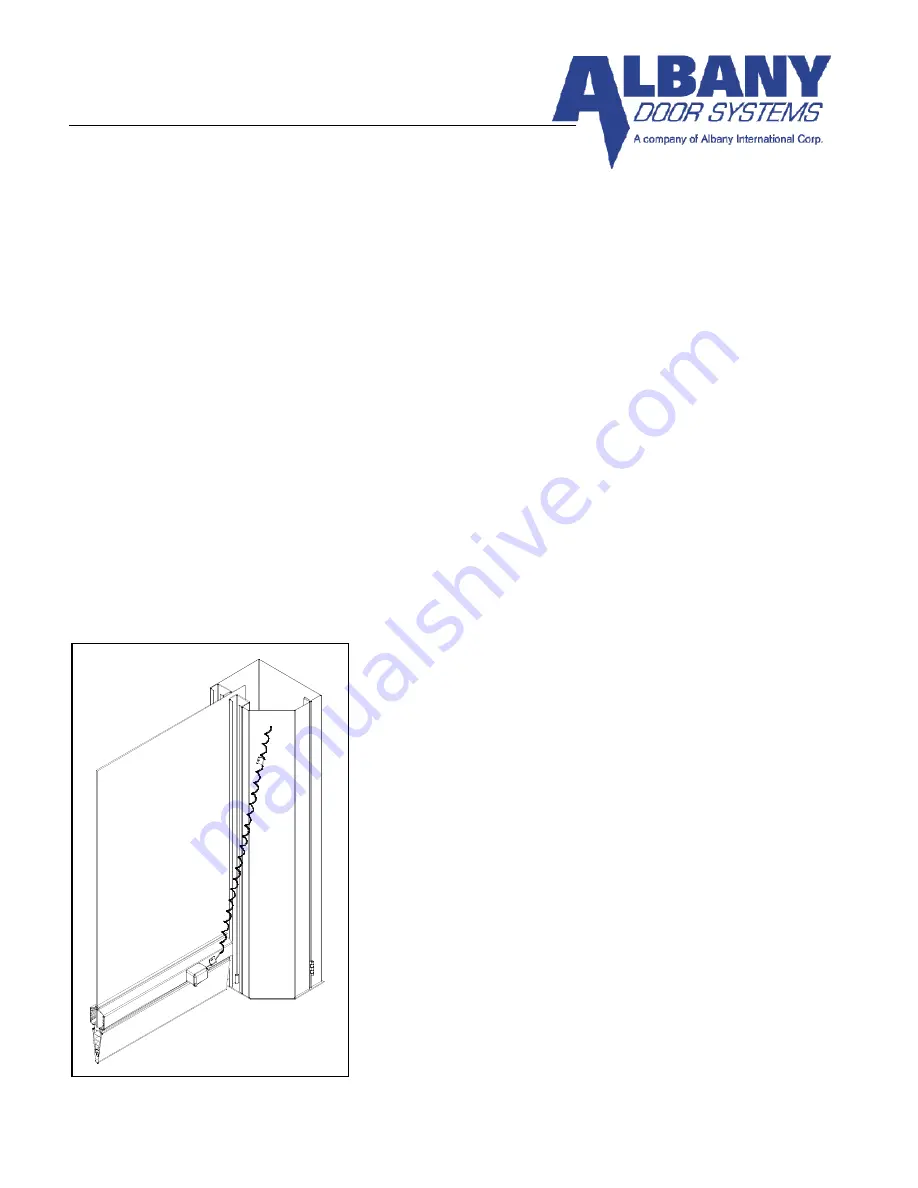
Mount the pressure switch enclosure on the bottom beam
using the hardware and holes provided. Attach the retractile cord
using the cable clamp on the bottom beam and the other to the
drive side frame (
Figure 15
). Insert clear plastic tube onto nipple
on pressure switch enclosure (
Figure 16
).
Step 9
Close both side frame covers and secure them using the
four locking pins provided (
Figure 17 Model 670
doors
)(
Figure 18 for Model 570 doors
).
FIGURE 11
FIGURE 15
Summary of Contents for RAPID-ROLL 570
Page 9: ...Part Number 6410T0006 Version 4 23 2010 9 FIGURE 3 FIGURE 4 FIGURE 5 ...
Page 21: ...Part Number 6410T0006 Version 4 23 2010 21 FIGURE 17 FIGURE 16 FIGURE 18 ...
Page 38: ...Part Number 6410T0006 Version 4 23 2010 38 Figure 37 ...
Page 42: ...Part Number 6410T0006 Version 4 23 2010 42 Figure 39A ...
Page 50: ...Part Number 6410T0006 Version 4 23 2010 50 FIGURE 45 Figure 46 ...


