Part N
umber
6410T0006
Version 4/23/2010
31
PACKING LIST
Cable chain, (2 pieces, length dependent upon height of door)
LH & RH C.S.E. guide bar assemblies
NOTE
REFERENCE FIGURE 30 WHILE PERFORMING THIS PROCEDURE
WARNING
ENSURE THE DOOR COUNTER BALANCE SYSTEM HAS BEEN INSTALLED AND
PROPERLY TENSIONED PRIOR TO PERFORMING THIS PROCEDURE.
1.
Place the bottom beam of the door at an accessible height (i.e. four feet off the ground). Thread
photocell cable through the plastic cable chain starting at the end, which contains the female chain
link. Perform this step for both photocells.
2.
Locate the pre-installed male clips on the C.S.E. guide bars. Attach one end of the cable chain to this
male clip.
3.
Remove the rubber stops from the top end of each guide bar. Slide the guide bars up into the white
polyethylene guides located on each end bracket. The photocells will be facing into the door opening,
towards each other. See
Figure 30
for proper orientation.
4.
Re-install rubber stops to the top ends of both guide bars.
5.
Feed the photocell cables through the pre-installed female cable chain clips inside the side frames.
6.
Manually move the C.S.E. guide bars up and down to verify smooth operation.
7.
Disengage the gearbox (or release brake if equipped with an All
Star™ pulse encoder drive unit),
and lower the door slowly until it is fully closed. The cable chains should loop down freely without
coming in contact with anything inside the side frames. If this is the case, then cable chain links must
be removed until proper length is achieved.
8.
Slowly lift the door until it is completely open. When the door is at its top limit, the cable chain
should not be taught.
ELECTRICAL INSTALLATION
Wire photocells according to the appropriate electrical schematics for your door. The wire terminations
inside the control panel will be same for either a standard PLC or All
Star™ setup. The C.S.E. system
itself is controlled by a photo amplifier box, which is pre-wired from the factory inside the control panel.
Reference drawing # LFX14CSE for a standard PLC and drawing # ALLCSE for an All
Star™ control
panel.
Summary of Contents for RAPID-ROLL 570
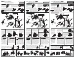
Page 9: ...Part Number 6410T0006 Version 4 23 2010 9 FIGURE 3 FIGURE 4 FIGURE 5 ...
Page 21: ...Part Number 6410T0006 Version 4 23 2010 21 FIGURE 17 FIGURE 16 FIGURE 18 ...
Page 38: ...Part Number 6410T0006 Version 4 23 2010 38 Figure 37 ...
Page 42: ...Part Number 6410T0006 Version 4 23 2010 42 Figure 39A ...
Page 50: ...Part Number 6410T0006 Version 4 23 2010 50 FIGURE 45 Figure 46 ...


