Part N
umber
6410T0006
Version 4/23/2010
43
MANUAL HOIST INSTALLATION
This option eliminates the drive unit and allows the door to
be operated manually via a manual hoist.
NOTE
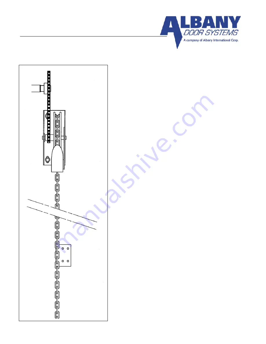
REFERENCE FIGURE 40 WHILE PERFORMING
THIS PROCEDURE
Mount manual hoist housing on wall a few inches below stub
axle on drive side of door.
Place supplied small key in keyway and attach the #41B12
sprocket to shaft on manual hoist housing. Tighten set screw
to secure sprocket in place. Place supplied larger key in
keyway on stub axle and attach the #41B54 sprocket onto
stub axle. While ensuring it is in line with the #41B12
sprocket, tighten set screw on sprocket.
Thread the #41 roller chain around both sprockets. Adjust
size of chain to enable it to ride securely on both sprockets by
removing links as necessary. Secure the chain by joining the
end links together.
Thread the hand chain through the chain guide holes and over
the pocket wheel. Secure the chain by joining the end links
together.
Mount hand chain locking plate on wall approximately five
feet above the floor.
NOTE
IT IS RECOMMENDED TO ALWAYS HAVE THE
CHAIN ENGAGED INTO THE CHAIN KEEPER
AFTER THE DOOR IS OPENED. THIS PREVENTS
THE DOOR FROM DRIFTING.
Figure 40
Summary of Contents for RAPID-ROLL 570
Page 9: ...Part Number 6410T0006 Version 4 23 2010 9 FIGURE 3 FIGURE 4 FIGURE 5 ...
Page 21: ...Part Number 6410T0006 Version 4 23 2010 21 FIGURE 17 FIGURE 16 FIGURE 18 ...
Page 38: ...Part Number 6410T0006 Version 4 23 2010 38 Figure 37 ...
Page 42: ...Part Number 6410T0006 Version 4 23 2010 42 Figure 39A ...
Page 50: ...Part Number 6410T0006 Version 4 23 2010 50 FIGURE 45 Figure 46 ...


