Part N
umber
6410T0006
Version 4/23/2010
47
Ensure the side frame covers are closed. Close the door fabric completely.
Attach the two windbar strap attachment blocks to the top of each windbar strap bracket using the
supplied #10-32 x ¾” cap screws (
view A-A
). Do not fully tighten the screws at this time.
Measure from the top edge of the bottom beam assembly to the top edge of the windbar channel on each
side frame cover and mark the centerline of this dimension on the inside of each windbar channel.
Insert the windbar from the top of the windbar channel. Lower the windbar and align the center of the bar
to the centerline marks made in Step #3 (
view B-B
). Attach C-clamps to the windbar channels to allow
them to rest at this position. Position the windbar straps between the door fabric and the windbar at this
time. For rear windbar mount, simply run the straps over the top to the backside of the door.
NOTE
WHEN INSTALLING THE WINDBAR STRAPS, REMOVE ANY TWISTS AND ENSURE
THAT NO FRAYING OCCURS IN THE WINDBAR STRAPS. DO NOT CUT WINDBAR
STRAPS UNTIL WINDBARS ARE COMPLETELY INSTALLED.
Working with one strap at a time, loop the outside right-hand strap around the bottom of the windbar and
bring it up to the strap bracket. Keeping the strap taught around the windbar, feed the end of the strap
through the right-hand strap clamp block, from front to back. Tighten down the #10-32 x ¾” cap screws
on the strap clamp (
view A-A
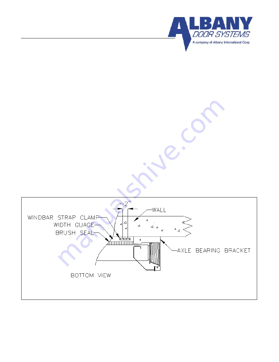
). For rear windbar mount, the clamping blocks are located on each side of
the width gauge (
Figure 43
). Follow this procedure for the three remaining straps and clamps.
Remove the C-clamps from the windbar channels and place a level across the center of the windbar.
Level the windbar and adjust straps accordingly.
Disengage the gearbox by rotating red handle counter clockwise or disengage the brake by pulling down
Figure 43
Summary of Contents for RAPID-ROLL 570
Page 9: ...Part Number 6410T0006 Version 4 23 2010 9 FIGURE 3 FIGURE 4 FIGURE 5 ...
Page 21: ...Part Number 6410T0006 Version 4 23 2010 21 FIGURE 17 FIGURE 16 FIGURE 18 ...
Page 38: ...Part Number 6410T0006 Version 4 23 2010 38 Figure 37 ...
Page 42: ...Part Number 6410T0006 Version 4 23 2010 42 Figure 39A ...
Page 50: ...Part Number 6410T0006 Version 4 23 2010 50 FIGURE 45 Figure 46 ...


