290 XF
36
Note: The diesel engines may have induction air heaters
to reduce smoke and improve cold weather
starting. These heaters cycle on and off every 20
to 30 seconds while the engines are warming up
and will cause the volt meters to fluctuate, The
fluctuation is particularly noticeable at idle. Once
the engines are started, monitor the volt meters
carefully. If one or both of the volt meters read
below 12 volts after one minute, raise the engine
RPM to 1200 for several seconds then return
them to idle. This will “excite” the alternators
and cause them to activate.
When in port or at anchor, the switch that supplies the port
engine should be off. Only the battery switch that activates
the starboard engine and house circuits should be on. This
will keep the port engine in reserve for starting the engines.
All three battery switches should be in the “OFF” position
when leaving the boat unattended.
Note: Current is supplied to the high water alarms and
the automatic float switches for the bilge pumps
when the batteries are connected and the battery
switches are off.
Your boat and engine charging system is designed for 12-
volt, lead acid, wet cell marine batteries. They will require
similar maintenance as those found in automobiles. Do not
attempt to use gel cell, absorbed wet mat or other non wet
cell batteries. The engine charging system is not designed
to recharge these batteries which could cause unusually short
battery life or engine starting problems. You also should not
mix the size or brand of the wet cell batteries. Always consult
your Albemarle dealer before changing the type of batteries
in your boat.
Engine Ignition Switches
Some ignition switches require keys and some are toggle
switches. The port switch activates the port engine and
the starboard switch activates the starboard engine. Most
switches have an off, on and momentary start position.
To start the engines, make sure the shift levers are in the
neutral position and your hand is on the throttle lever in the
idle position. Turn the key or move the switch to the start
position. When the engine starts release the switch and it will
automatically return to the run position. Stop the engine by
turning the switch to the off position. The ignition switches
are protected by the main breaker located on the engine and
breakers in the cabin DC breaker panels.
Note: Some Diesel engines use a separate stop switch to
turn off the fuel and stop the engine. If your boat is equipped
with diesel engines and stop switches, make sure that you
leave the ignition switches on until the engines are stopped.
The alternator could be damaged if the ignition switches are
turned off while the engines are running.
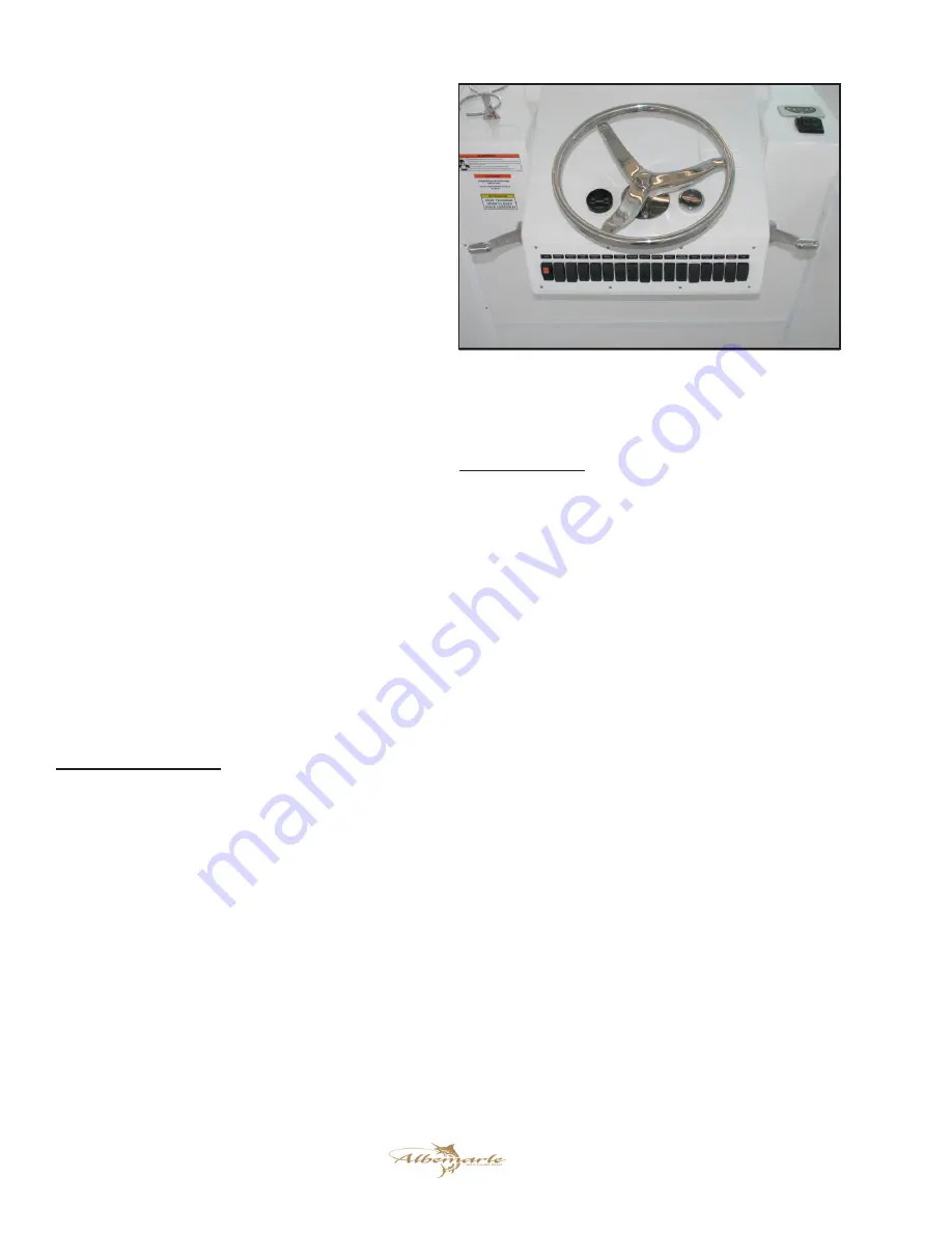
Helm Switch Panel
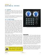
The main accessory switch panel is located on the helm
below the steering wheel. The circuit breakers that protect
the accessories and activate the engine starting circuits are
located in cabin breaker panels.
The rocker switches in the main accessory switch panel are
equipped with LED lights that illuminate when the accessory
controlled by the switch is activated. The following is a
description of the accessories controlled by the main accessory
switch panel:
Engine Controls
Activates and deactivates the engine controls. While the boat
is tied up at the dock and not in use, it is recommended that the
engine control system be turned off. Since power is supplied
directly to the engine control processor from power sources in
the engine room, turning power to the engine controls ON and
OFF in the engine room may be difficult to do each time the
system is started up. This switch allows power to the engine
control system to be turned ON or OFF at the main helm
station. Always make sure the engine controls are activated
before starting the engines.
Overhead Lights (Optional)
Activates the lights in the optional hardtop that illuminate the
bridge deck.
Navigation Lights
The switch is a three-position switch. The middle position is
“OFF.” Moving the switch in one direction will activate the
navigation lights. Moving the switch in the opposite direction
activates the anchor light.
Cockpit Lights
Activates the lights that illuminate the cockpit area.
Helm and Helm Switch Panel
Summary of Contents for 290 EXPRESS FISHERMAN
Page 2: ...290 XF 2 Print Date 4 07 2009 THIS PAGE WAS LEFT BLANK INTENTIONALLY...
Page 6: ...290 XF 6 THIS PAGE WAS LEFT BLANK INTENTIONALLY...
Page 8: ...290 XF 8 THIS PAGE WAS LEFT BLANK INTENTIONALLY...
Page 10: ...290 XF 10 THIS PAGE WAS LEFT BLANK INTENTIONALLY...
Page 22: ...290 XF 22 THIS PAGE WAS LEFT BLANK INTENTIONALLY...
Page 28: ...290 XF 28 THIS PAGE WAS LEFT BLANK INTENTIONALLY...
Page 34: ...290 XF 34 THIS PAGE WAS LEFT BLANK INTENTIONALLY...
Page 56: ...290 XF 56 THIS PAGE WAS LEFT BLANK INTENTIONALLY...
Page 80: ...290 XF 80 THIS PAGE WAS LEFT BLANK INTENTIONALLY...
Page 88: ...290 XF 88 THIS PAGE WAS LEFT BLANK INTENTIONALLY...
Page 91: ...91 290 XF...
Page 104: ...290 XF 104 THIS PAGE WAS LEFT BLANK INTENTIONALLY...
Page 110: ...290 XF 110 THIS PAGE WAS LEFT BLANK INTENTIONALLY...
Page 112: ...290 XF 112 MAINTENANCE LOG Hours Date Dealer Service Repairs...
Page 113: ...113 290 XF MAINTENANCE LOG Hours Date Dealer Service Repairs...
Page 114: ...290 XF 114 MAINTENANCE LOG Hours Date Dealer Service Repairs...
Page 115: ...115 290 XF MAINTENANCE LOG Hours Date Dealer Service Repairs...
Page 116: ...290 XF 116 MAINTENANCE LOG Hours Date Dealer Service Repairs...
Page 118: ...290 XF 118 THIS PAGE WAS LEFT BLANK INTENTIONALLY...
Page 119: ...119 290 XF Appendix C BOATING ACCIDENT REPORT...
Page 120: ...290 XF 120 BOATING ACCIDENT REPORT...
Page 121: ...121 290 XF...
Page 122: ...290 XF 122 THIS PAGE WAS LEFT BLANK INTENTIONALLY...
Page 133: ...133 290 XF THIS PAGE WAS LEFT BLANK INTENTIONALLY...
Page 134: ...Albemarle Boats 140 Midway Dr P O Box 349 Edenton NC 27932...


