290 XF
38
Additional Accessory Switch Panels
Additional switch panels are located in various locations in the
cockpit or cabin. The following is a description of additional
panels that may be on your Albemarle and the accessories
they control:
Trim Tab Switch Panel
Located in helm pod near the steering wheel and in the
optional tower helm. This switch controls the trim tab planes
located on the transom of the boat. Please refer to Chapter
2 for detailed information on the operation of the trim tab
controls.
Holding Tank Macerator
The holding tank overboard discharge macerator switch panel
is located in the head compartment next to the holding tank
monitor. It is a momentary switch that activates the overboard
macerator discharge system for the holding tank. Refer to
the Marine Head System in the Interior Equipment chapter
for additional information on the operation of the overboard
macerator discharge system.
Electric Engine Hatch Lift Switch
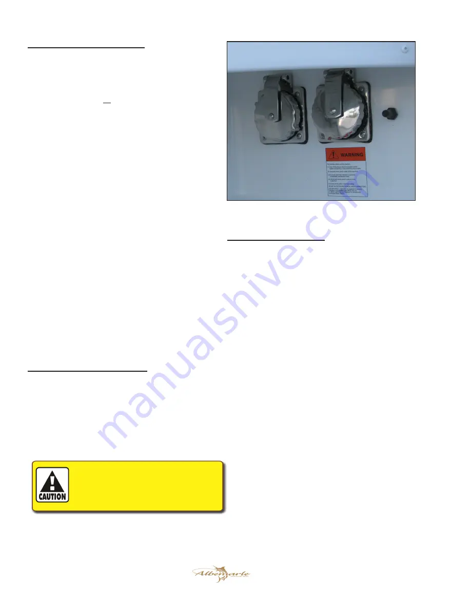
A momentary switch in the cockpit below the port gunnel near
the shore power inlet plug that controls the electric actuator
for the engine hatch. Move the switch up to raise the hatch
and move the switch down to lower the hatch. The switch
will automatically move to the center or off position and
the hatch will stop when the switch is released. Refer to the
Exterior Equipment chapter for additional information on the
engine hatch lifter. Note that the Starboard Engine battery
switch, Electric Hatch switch in the helm and the Electric
Hatch breaker in the cabin DC panel must be turned on for
the hatch lifter to operate.
Cabin DC Accessory Breaker Panels
Power is distributed to most of the 12-volt accessories through
individual circuit breakers located in the cabin DC breaker
panels. There are two DC breaker panels, one in the battery
switch panel and the main DC breaker panel. The breaker
panels are located near the companionway door. Some 12-
volt accessories are operated directly by the circuit breaker
in the panels while others are operated by switches fed by the
panel breakers.
PROPER FUSE OR bREAKER PROTECTION MUST
bE PROVIDED FOR ALL 12-VOLT EQUIPMENT
ADDED. DO NOT OVERLOAD THE ACCESSORY
CIRCUIT bREAKERS OR OTHER CIRCUITRY
THROUGH ADDITIONAL 12-VOLT EQUIPMENT.
Battery Switch Breaker Panel
The following is a description of the accessories controlled by
the “Push to Reset” DC breakers in the battery switch panel
located in the cabin wall near the steps:
Port Batt Condition
Provides protection and power for the 12-volt circuit to the
battery condition test switch for the port engine battery.
Starboard Batt Condition
Provides protection and power for the 12-volt circuit to the
battery condition test switch for the starboard engine/house
battery.
Generator Battery Condition
Provides protection and power for the 12-volt circuit to the
battery condition test switch for the generator battery.
Port Battery Parallel
Provides protection and power for the port engine and generator
battery parallel circuit activated by the Generator Parallel
switch in the cabin. This “push to reset” breaker is supplied
current when the port battery switch is activated.
Stbd Battery Parallel
Provides protection and power for the engine battery parallel
circuit activated by the Battery Parallel switch on the helm
switch panel. This “push to reset” breaker is supplied current
when the Starboard Engine battery switch is activated.
Generator Parallel
Provides protection and power for the port engine and generator
battery parallel circuit activated by the Generator Parallel
switch in the cabin. This “push to reset” breaker is supplied
current when the generator battery switch is activated.
AC Inlet and Electric Hatch Lift Switch
Summary of Contents for 290 EXPRESS FISHERMAN
Page 2: ...290 XF 2 Print Date 4 07 2009 THIS PAGE WAS LEFT BLANK INTENTIONALLY...
Page 6: ...290 XF 6 THIS PAGE WAS LEFT BLANK INTENTIONALLY...
Page 8: ...290 XF 8 THIS PAGE WAS LEFT BLANK INTENTIONALLY...
Page 10: ...290 XF 10 THIS PAGE WAS LEFT BLANK INTENTIONALLY...
Page 22: ...290 XF 22 THIS PAGE WAS LEFT BLANK INTENTIONALLY...
Page 28: ...290 XF 28 THIS PAGE WAS LEFT BLANK INTENTIONALLY...
Page 34: ...290 XF 34 THIS PAGE WAS LEFT BLANK INTENTIONALLY...
Page 56: ...290 XF 56 THIS PAGE WAS LEFT BLANK INTENTIONALLY...
Page 80: ...290 XF 80 THIS PAGE WAS LEFT BLANK INTENTIONALLY...
Page 88: ...290 XF 88 THIS PAGE WAS LEFT BLANK INTENTIONALLY...
Page 91: ...91 290 XF...
Page 104: ...290 XF 104 THIS PAGE WAS LEFT BLANK INTENTIONALLY...
Page 110: ...290 XF 110 THIS PAGE WAS LEFT BLANK INTENTIONALLY...
Page 112: ...290 XF 112 MAINTENANCE LOG Hours Date Dealer Service Repairs...
Page 113: ...113 290 XF MAINTENANCE LOG Hours Date Dealer Service Repairs...
Page 114: ...290 XF 114 MAINTENANCE LOG Hours Date Dealer Service Repairs...
Page 115: ...115 290 XF MAINTENANCE LOG Hours Date Dealer Service Repairs...
Page 116: ...290 XF 116 MAINTENANCE LOG Hours Date Dealer Service Repairs...
Page 118: ...290 XF 118 THIS PAGE WAS LEFT BLANK INTENTIONALLY...
Page 119: ...119 290 XF Appendix C BOATING ACCIDENT REPORT...
Page 120: ...290 XF 120 BOATING ACCIDENT REPORT...
Page 121: ...121 290 XF...
Page 122: ...290 XF 122 THIS PAGE WAS LEFT BLANK INTENTIONALLY...
Page 133: ...133 290 XF THIS PAGE WAS LEFT BLANK INTENTIONALLY...
Page 134: ...Albemarle Boats 140 Midway Dr P O Box 349 Edenton NC 27932...


