19
4
10 Convertible
Propeller Shaft Alignment
The propeller shaft coupling and the transmission coupling
should be checked for proper alignment beginning with the first
launching, again after 20 hours of engine operation, and annu-
ally thereafter. The alignment should especially be checked if
noise or vibration occurs.
Excessive vibration, abnormal strut bearing wear, or broken
propeller shaft coupling bolts are an indication of misalignment.
Misalignment can also cause severe damage to the shaft log,
strut, shaft and the engine transmission. Realignment should
only be performed by a qualified service person.
The correct procedure for checking the shaft alignment so a
boat owner can determine if service work is required, is as
follows:
Step 1:
Remove the bolts that secure the propeller shaft
flanges.
Step 2:
Hold the propeller shaft flange firmly against the
transmission flange.
Step 3:
Try to insert a .004” feeler gauge at the top, the
bottom and at both sides between the flanges. If
it can be easily inserted between the flanges in any
area, try inserting a larger feeler gauge until you
determine the amount of variance.
Step 4:
While holding the transmission flange, turn the
prop shaft 90 degrees and repeat step 3. A straight
shaft in proper alignment will not allow the inser-
tion of a feeler gauge larger than .004”, regardless
of the prop shaft position.
Step 5:
If a gap larger than .004” is found and the gap
moves as the shaft flange is rotated, the flange or
the prop shaft is bent out of tolerance and must
be replaced or removed and straightened. If the
gap remains at the same position regardless of the
propeller shaft rotated position, the engine must
be realigned. At this point, an Albemarle dealer
should be contacted.
NOTE: The boat should always be at rest in the water when
checking or aligning the propeller shaft.
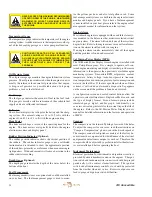
MAKE SURE THE PROPELLER SHAFT FLANGE
BOLTS ARE TIGHTENED SECURELY AFTER
CHECKING THE ENGINE ALIGNMENT AND BEFORE
OPERATING THE BOAT.
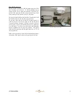
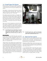
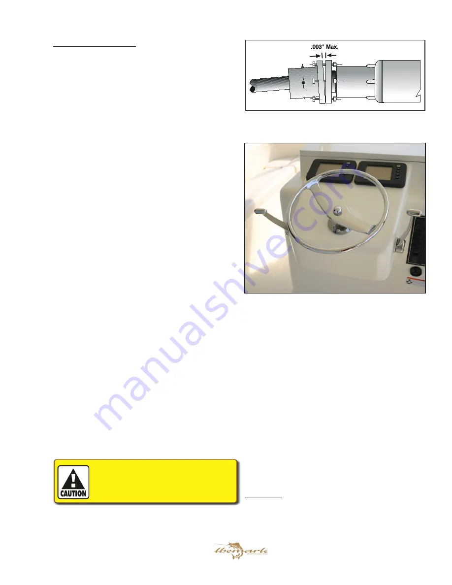
Propeller Shaft Coupling
NOTE: Lifting the boat with lifting straps over the prop
shafts will cause the shafts to become bent. Always
position lifting straps so they are clear of the run-
ning gear.
1.8 Engine Instrumentation
The helm station is equipped with a set of engine instruments
and/or alarms. These instruments allow the pilot to monitor
the engine operational conditions. Close observation of these
instruments allows the pilot to operate the engines at the most
efficient level and could save the engines from serious costly
damage. The instrumentation is unique to the type of inboard
motors installed on your Albemarle and is typically built into
the electronic engine monitor and display system. Some or all
of the following gauges may be present.
Tachometer
The tachometer displays the speed of the engine in revolutions
per minute (RPM). This speed is not the boat speed nor nec-
essarily the speed of the propeller. The tachometer may not
register zero with the key in the “OFF” position.
Cat Marine Power Display (MPD)
Summary of Contents for 41 CONVERTIBLE
Page 1: ...41 CONVERTIBLE Albemarle Boats 140 Midway DR P O Box 349 Edenton NC 27932 OWNER S MANUAL...
Page 2: ...410 Convertible 2 Print Date 6 2006 THIS PAGE WAS LEFT BLANK INTENTIONALLY...
Page 6: ...410 Convertible 6 THIS PAGE WAS LEFT BLANK INTENTIONALLY...
Page 8: ...410 Convertible 8 THIS PAGE WAS LEFT BLANK INTENTIONALLY...
Page 10: ...410 Convertible 10 THIS PAGE WAS LEFT BLANK INTENTIONALLY...
Page 26: ...410 Convertible 26 THIS PAGE WAS LEFT BLANK INTENTIONALLY...
Page 44: ...410 Convertible 44 THIS PAGE WAS LEFT BLANK INTENTIONALLY...
Page 52: ...410 Convertible 52 THIS PAGE WAS LEFT BLANK INTENTIONALLY...
Page 56: ...410 Convertible 56 THIS PAGE WAS LEFT BLANK INTENTIONALLY...
Page 60: ...410 Convertible 60 THIS PAGE WAS LEFT BLANK INTENTIONALLY...
Page 68: ...410 Convertible 68 THIS PAGE WAS LEFT BLANK INTENTIONALLY...
Page 90: ...410 Convertible 90 THIS PAGE WAS LEFT BLANK INTENTIONALLY...
Page 96: ...410 Convertible 96 THIS PAGE WAS LEFT BLANK INTENTIONALLY...
Page 102: ...410 Convertible 102 THIS PAGE WAS LEFT BLANK INTENTIONALLY...
Page 103: ...103 410 Convertible Appendix A SCHEMATICS 12 volt DC...
Page 104: ...410 Convertible 104 AC Shore to Panel wiring...
Page 105: ...105 410 Convertible AC Breaker Panel...
Page 106: ...410 Convertible 106 DC Battery Switch Panel...
Page 107: ...107 410 Convertible Batteries and Cables...
Page 108: ...410 Convertible 108 Hydraulic Steering...
Page 109: ...109 410 Convertible Engine Control System...
Page 110: ...410 Convertible 110 Fuel System...
Page 111: ...111 410 Convertible Fuel Valves...
Page 112: ...410 Convertible 112 Fresh Water System...
Page 113: ...113 410 Convertible Sea Water Systems...
Page 114: ...410 Convertible 114 Drainage System...
Page 115: ...115 410 Convertible Rudder Assembly Coupler Assembly Shaft Transmission Coupler Shaft Coupler...
Page 116: ...410 Convertible 116 Shaft Seal Assembly Prop Assembly Shaft Propeller Key Prop Nuts Cotter Key...
Page 117: ...117 410 Convertible Sling Locations...
Page 118: ...410 Convertible 118 Cradle and Blocking positions...
Page 120: ...410 Convertible 120 MAINTENANCE LOG Hours Date Dealer Service Repairs...
Page 121: ...121 410 Convertible MAINTENANCE LOG Hours Date Dealer Service Repairs...
Page 122: ...410 Convertible 122 MAINTENANCE LOG Hours Date Dealer Service Repairs...
Page 123: ...123 410 Convertible MAINTENANCE LOG Hours Date Dealer Service Repairs...
Page 124: ...410 Convertible 124 MAINTENANCE LOG Hours Date Dealer Service Repairs...
Page 126: ...410 Convertible 126 THIS PAGE WAS LEFT BLANK INTENTIONALLY...
Page 137: ...137 410 Convertible THIS PAGE WAS LEFT BLANK INTENTIONALLY...
Page 138: ...410 Convertible 138 Albemarle Boats 140 Midway Dr P O Box 349 Edenton NC 27932...

