65
4
10 Convertible
helm. Make sure to monitor the water level in the fishbox and
turn the pump off as soon as pumping is complete. The pump
will be damaged if it is allowed to run dry for more than a few
seconds. The fishbox should be pumped out and cleaned after
each use. Refer to the Drainage Systems chapter for more
information on the fishbox drainage.
Transom Fishbox
Another insulated fishbox is located in the center of the transom
gunnel. The fishbox is drained by gravity to an overboard thru-
hull fitting in the transom. It is accessed through two hatches
in the stern gunnel.
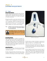
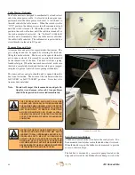
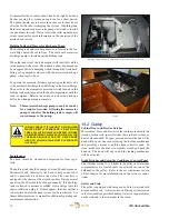
Cabin Door
The cabin door is made of Fiberglass. A lockable latch secures
the door and hatch in the closed position. A special latch se-
cures the door in the open position.
It is very important that the cabin door is secured properly in
the open or closed position. The door is heavy and if the door
is not properly latched, it could swing when the boat rocks and
pinch someone’s fingers between the door and the bulkhead or
damage the door. Always make sure the door is properly latched
in the open or closed position before operating the boat.
ALWAYS SECURE CABIN DOORS/HATCH
WHENEVER VESSEL IS IN MOTION OR IN ROUGH
WATER CONDITIONS.
9.4 Flybridge and Helm
Helm
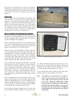
The steering, engine controls, engine instruments and switches
for exterior equipment and navigation lights are located on the
helm station. The helm station is located in the center of the
flybridge to provide improved visibility, more room for elec-
tronics and a more functional flybridge arrangement.
The steering helm and engine controls are located on the rear of
the center console. The helm switch panel is on the starboard
side of the helm and the engine run/stop switches, the engine
start switches and trim tab switches are located on a separate
panel below the steering wheel.
The Molded-in, retractable electronics storage is located
forward of the engine controls. Electric actuators controlled
by a switch in the helm raise or lower the modules. Access
to service the controls or to install or service electronics is
provided through a door in the helm.
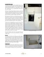
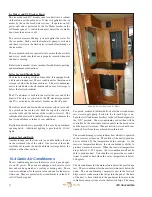
Standard Helm Seats
The helm seats are pedestal seats that swivel and adjust fore and
aft. The seat height on the pedestal is also adjustable.
There are two levers and one tension knob on the seat base.
Lifting the lever located at the front of the seat base allows the
seat to be adjusted fore and aft. Releasing the lever locks the
seat in that position. Lifting the lever on the starboard side of
the seat base releases the pivot lock and allows the helm seat to
be swiveled on the pedestal. The helm seat will automatically
lock when it is swiveled back to the operating position. The
friction knob adjusts the tension of seat base on the pedestal
and is also located on the port side of the seat. It should be
adjusted to allow the seat to be swiveled when the swivel lock
is released and tight enough to eliminate play between the seat
base and the pedestal.
The pedestal height can be changed by pulling the spring loaded
release pin on the pedestal and sliding it up or down to the next
preset position. Release the pin as the pedestal is sliding and
the pin will automatically lock into place.
Teak Helm Chair (Optional)
The helm seat is a pedestal seat that swivels and adjusts fore
and aft. The height of the footrest on the pedestal is also
adjustable.
There is one tension adjuster and a spring loaded lever on the
seat base. Lifting the lever located at the front of the seat base
allows the seat to be adjusted fore and aft. Releasing the lever
locks the seat in that position. Loosening the tension adjuster
on the starboard side of the seat base allows the helm seat to
be swiveled on the pedestal. The tension can be adjusted to
lock the seat in the desired position or control how easily the
seat will swivel. It should always be adjusted tight enough to
eliminate play between the seat base and the pedestal.
The pedestal footrest height can be changed by loosening the
tension adjuster on the port side of the footrest and sliding it
up or down to the desired position. It is important to make
sure the footrest is set parallel to the tension adjuster handle
before adjusting the tension and that the handle is rotated down
before swiveling the footrest. Otherwise, the handle will hit
the footrest when it is rotated and damage the finish.
Helm
Summary of Contents for 41 CONVERTIBLE
Page 1: ...41 CONVERTIBLE Albemarle Boats 140 Midway DR P O Box 349 Edenton NC 27932 OWNER S MANUAL...
Page 2: ...410 Convertible 2 Print Date 6 2006 THIS PAGE WAS LEFT BLANK INTENTIONALLY...
Page 6: ...410 Convertible 6 THIS PAGE WAS LEFT BLANK INTENTIONALLY...
Page 8: ...410 Convertible 8 THIS PAGE WAS LEFT BLANK INTENTIONALLY...
Page 10: ...410 Convertible 10 THIS PAGE WAS LEFT BLANK INTENTIONALLY...
Page 26: ...410 Convertible 26 THIS PAGE WAS LEFT BLANK INTENTIONALLY...
Page 44: ...410 Convertible 44 THIS PAGE WAS LEFT BLANK INTENTIONALLY...
Page 52: ...410 Convertible 52 THIS PAGE WAS LEFT BLANK INTENTIONALLY...
Page 56: ...410 Convertible 56 THIS PAGE WAS LEFT BLANK INTENTIONALLY...
Page 60: ...410 Convertible 60 THIS PAGE WAS LEFT BLANK INTENTIONALLY...
Page 68: ...410 Convertible 68 THIS PAGE WAS LEFT BLANK INTENTIONALLY...
Page 90: ...410 Convertible 90 THIS PAGE WAS LEFT BLANK INTENTIONALLY...
Page 96: ...410 Convertible 96 THIS PAGE WAS LEFT BLANK INTENTIONALLY...
Page 102: ...410 Convertible 102 THIS PAGE WAS LEFT BLANK INTENTIONALLY...
Page 103: ...103 410 Convertible Appendix A SCHEMATICS 12 volt DC...
Page 104: ...410 Convertible 104 AC Shore to Panel wiring...
Page 105: ...105 410 Convertible AC Breaker Panel...
Page 106: ...410 Convertible 106 DC Battery Switch Panel...
Page 107: ...107 410 Convertible Batteries and Cables...
Page 108: ...410 Convertible 108 Hydraulic Steering...
Page 109: ...109 410 Convertible Engine Control System...
Page 110: ...410 Convertible 110 Fuel System...
Page 111: ...111 410 Convertible Fuel Valves...
Page 112: ...410 Convertible 112 Fresh Water System...
Page 113: ...113 410 Convertible Sea Water Systems...
Page 114: ...410 Convertible 114 Drainage System...
Page 115: ...115 410 Convertible Rudder Assembly Coupler Assembly Shaft Transmission Coupler Shaft Coupler...
Page 116: ...410 Convertible 116 Shaft Seal Assembly Prop Assembly Shaft Propeller Key Prop Nuts Cotter Key...
Page 117: ...117 410 Convertible Sling Locations...
Page 118: ...410 Convertible 118 Cradle and Blocking positions...
Page 120: ...410 Convertible 120 MAINTENANCE LOG Hours Date Dealer Service Repairs...
Page 121: ...121 410 Convertible MAINTENANCE LOG Hours Date Dealer Service Repairs...
Page 122: ...410 Convertible 122 MAINTENANCE LOG Hours Date Dealer Service Repairs...
Page 123: ...123 410 Convertible MAINTENANCE LOG Hours Date Dealer Service Repairs...
Page 124: ...410 Convertible 124 MAINTENANCE LOG Hours Date Dealer Service Repairs...
Page 126: ...410 Convertible 126 THIS PAGE WAS LEFT BLANK INTENTIONALLY...
Page 137: ...137 410 Convertible THIS PAGE WAS LEFT BLANK INTENTIONALLY...
Page 138: ...410 Convertible 138 Albemarle Boats 140 Midway Dr P O Box 349 Edenton NC 27932...


