IMPORTANT NOTE
Albentia Systems declares that this equipment complies with the essential requirements and other relevant demands established in the Directive 1995/5/EC. CE Marking
ensures the free movement of the product within the EU and EFTA single market (total 30 countries). A copy of the “Declaration of Conformity (DoC)” document may be
obtained in this link:
http: //www.albentia.com/Docs/CEcompliance.pdf
X1
X1
7.
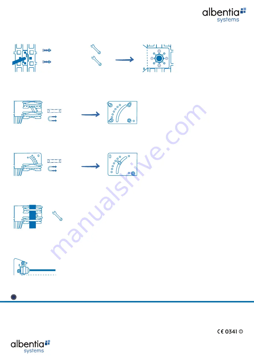
MOUNTING THE RF CABLE
5.
MOUNTING THE U-HARDWARE FOR ADJUSTABLE LIFTING
4.
ASSEMBLY OF THE HARDWARE IN U FOR ELEVATION 0º
* The arrows marked POL should line up
with the grid.
3.
MOUNTING THE ILLUMINATOR
* Rear of the antenna.
X2
X2
* Place the washers and nuts on the side inside of the
hardware: flat at the bottom and thick at the top.
* Place the washers and nuts on the side inside of the
hardware: flat at the bottom and thick at the top.
6.
MOUNTING ON THE MAST
* Vulcanize the connector.
X2 M5x30 24 dBi
X2 M6x30 30 dBi
10
8
10
Albentia Systems S.A.
C/ Margarita Salas, 22 - 28918 Leganés - Madrid (SPAIN)
Tel.: +34 91 440 0213
Fax: +34 91 327 4362
E-mail: sales@albentia.com
www.albentia.com
ACC-A24/30R-S INSTALLATION GUIDE
All Albentia Systems products are designed and manufactured in the European Union


