Manuale istruzioni
-FKC 65 UB
01/01/19 Rev: 1.0.0
40
14.4 ELECTRICAL CONTROL DEVICE
FKC 65 UB
14.4.1
PLATE
OF
RESETTABLE
THERMAL
CIRCUIT
BREAKERS OF THE MOTOR (only FKC 65 UB )
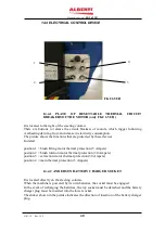
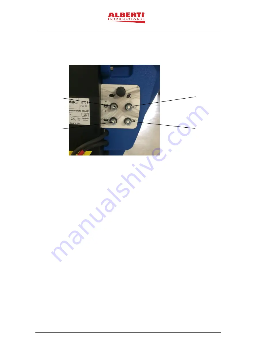
It is located to the right of the steering column.
There are buttons to release the circuit breakers of motors, which trigger following
overheating deriving from an increase in electricity consumption.
The picture shows the functions that are protected by these devices.
In detail:
position 1 = brush lifting motor thermal protection (5 Ampere)
position 2 = brush rotation motor thermal protection (30 Ampere)
position 3 = extraction motor thermal protection (30 Ampere)
position 4 = main thermal protection (5 Ampere)
14.4.2
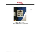
ANDERSON BATTERY CHARGER SOCKET
It is located directly on the steering column.
When the machine is powered by its own batteries, the socket must be engaged.
In the event of recharging the batteries, the top socket must be detached and the battery
charger plug must be inserted into the lower socket.
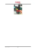
The sticker shown in the picture indicates the direction of insertion of the battery charger
plug.
1
2
3
4
Summary of Contents for FKC 65 UB
Page 13: ...Manuale istruzioni FKC 65 UB 01 01 19 Rev 1 0 0 13 3 1 Dimensions...
Page 15: ...Manuale istruzioni FKC 65 UB 01 01 19 Rev 1 0 0 15 1 7 8 9 10 12 15 19 20 18 24...
Page 27: ...Manuale istruzioni FKC 65 UB 01 01 19 Rev 1 0 0 27...
Page 41: ...Manuale istruzioni FKC 65 UB 01 01 19 Rev 1 0 0 41...
Page 54: ...Manuale istruzioni FKC 65 UB 01 01 19 Rev 1 0 0 54...


