background image


4

–3


PRE-OPERATION CHECKS  
 

 : Exhaust gas is lethal. The exhaust 

of all engines contains carbon monoxide 
(CO); this odorless, colorless and poisonous 
gas cause unconsciousness and death in a 
short time.  


The symptoms of carbon monoxide (CO) 
poisoning are given below: 


Dizziness 


Headache  


Nausea 


Weakness and sleepiness 


Vomiting  


Losing consciousness 

 
IMMEDIATELY GET INTO OPEN AIR IF YOU 
ENCOUNTER ANY OF THESE SYMPTOMS. 
Ask for medical attention if the symptoms are 
continued. Stay in open air until you get 
medical attention.


Always check the exhaust system visually 
and manually before any work. Inspect and 
check entire exhaust system for leaks every 
time you operate the generator and every 
eight hours of operation. Do not operate the 
generator set until the leak is repaired. 
Installation of the exhaust system shall 
always be performed according to the 
instructions of the manufacturer. 


Check the generator set as specified in 
GENERAL MAINTENANCE (page 5-1) section 
before daily operation and after every eight hours 
of operation.  


1.  Ensure that all carbon monoxide (CO) 

detectors on your vessel are in operating 
condition. 
 

2.  Check if there are any swimmers on the 

sea who can be subject to the exhaust 
and warn them. 


3.  Close the switches of all electrical loads. 


PREPARATION OF THE FUEL SYSTEM FOR 
USING 

Fuel system shall be prepared for operation after 
the fuel filter is changed or fuel of generator 
system is out. Remove the lead terminals after 
turn off your generator to prepare your fuel 
system. While you are opening terminals of the 
battery cables to decrease any arcs, always 
disconnect the negative (-) battery cable firstly, 
and re-connect the negative   (-) battery cable 
lastly.


OPERATING THE GENERATOR SET 

Generator set may operate or stop by a manual 
control panel or an electronic remote control 
panel. 


Operating the Generator Set By the Manual 
Control Panel   


1- 

Bring the control switch on panel placed 
on the generator set to MANUAL position, 
press on 2 

– 3 seconds start switch for 

sending starting signal and so generator 
will be running.  (Page 3-1, Figure 2)


2- 

For a longer service life, wait for 2 to 3 
minutes the heating of the engine before 
connecting to the A/C and other high 
electrical loads.                                                                           


3- 

Check for any engine coolant, fuel and 
exhaust leaks. Immediately stop the 
generator set if there is any leak. Repair 
the leakages immediately in a proper way. 
Do not operate your generator before 
repairing the leaks that may occur on 
connection points, hoses and pipes.


4- 

Fault lamp will be burn on the panel if the 
generator set cannot be operated. See the 
Troubleshooting section, and perform 
necessary maintenance and repairs. 
Contact ALTINBOĞA MAKİNA SANAYİ 
TİCARET A.Ş. (www.albomarine.com) for 
consulting with the authorized service 
personnel on the resolution using the 
following phone number: +90(212) 612 25 
00 pbx.


Stopping the Generator Set  

Always turn off all electrical loads before stopping 
the generator. Generator shall be operated for 2 
minutes with no load, then turn the control switch 
to STOP position, display status lamps of the 
generator set will be burn out and engine will be 
stop. 


Operating  the  Generator  Set  with  Electronic 
Remote Control Panel (Remote Start)   


1. 

Bring the start-stop switch on the manual 
control panel to ON position. (Page 3-1, 
Figure 2)


2. 

Press the “RUN” button on the Electronic 
Remote Control Panel of which light being 
on remote start lamp. Engine will start 
automatically in 3 seconds.                        
(Page 3-1, Figure 2)


3. 

Fault status lamp will be burn out if the 
generator set cannot be operated. See 
the Troubleshooting section (Page 6-2), 
and perform necessary maintenance and 
repairs.


Summary of Contents for MG 309

Page 1: ...G 314 MG 315 MG 320 MG 323 MG 330 TN 307 TS 309 TS 315 TS 320 TS 323 TS 330 TS 343 Models Operation Manual PLEASE READ AND KEEP THIS MANUAL CAREFULLY MN 305 MN 307 MS 306 MS 307 MS 310 MS 312 MS 316 MS 323 MS 330 TG 306 TG 309 TG 311 TG 314 TG 315 TG 316 TG 320 TG 323 TG 330 TG 343 ...

Page 2: ...olu Demirciler Çarşısı 1 Baltaş San Sitesi No 10 37 Zeytinburnu İSTANBUL Telephone 90 212 612 25 00 90 212 612 00 48 Web http www altinboga com http www albomarine com E mail altinboga altinboga com Model Serial No Product identification information ...

Page 3: ...pping the Generator Set 4 3 Emergency Stop 4 4 Loading the Generator Set 4 4 No Load Starting 4 4 Circuit Breaking Fuses 4 5 Connecting to Main Supply 4 5 Operating Against Freezing Danger 4 5 Maintenance of a New or Overhauled Engine 4 5 Stand By Operation of the Generator Set 4 5 Storing Conditions for the Generator Set 4 6 5 PERIODICAL MAINTENANCE 5 1 General Maintenance 5 2 Maintenance of the ...

Page 4: ......

Page 5: ...eas of the vessel when a gas leak is detected and an ambulance shall be called when it is necessary Operate the generator set after the repair of the exhaust gas leak GENERATOR VOLTAGE IS LETHAL All power control cables and connecting elements that will be connected externally to the generator shall be connected by a trained and experienced technician according to the current legislation and manuf...

Page 6: ...No 10 DENSE FUEL VAPOR IN CLOSED AREAS MAY CAUSE DIESEL ENGINE OVERSPEED RUNNING Always perform necessary checks before starting to operate the generator Never operate your generator when there is a fuel seepage gobbing leak or dense fuel vapor in closed areas Dense fuel vapor inside of closed areas may cause diesel engine to overspeed running to stop roughly and late So explosions fires and damag...

Page 7: ...ormed by authorized service personnel according to the PERIODICAL MAINTENANCE CHART Page 5 1 Table 2 as specified in the manual Keep this manual near the generator to refer to it when required This generator set is not a life support system It may be stopped abruptly without any warning Children persons with physical and mental disabilities and pets may be affected in this case with serious person...

Page 8: ...Battery charge voltage gauge indicates whether the battery is charged from the engine and voltage status of the battery 4 Operating time clock indicates total amount of hours operating time of the generator 5 Malfunction indicator lamp is turned by reason of faults that may occur during the operation of the generator It is turned off when the generator is operated after the fault is repaired 6 Sta...

Page 9: ... until the generator is started Device starts to monitor internal protections and external alarm inputs when the engine run Only first occurring alarm is considered alarms that are occurring later are not displayed Engine is stopped if Stop button is pressed or REMOTE START signal is deactivated Figure 3 DKG114 module has several features like Operating stopping the generator both remotely and man...

Page 10: ... FAULT AND SOLVING PROBLEMS Page 6 1 and counting please refer to Emergency Stop Button and DC Circuit Breaker Press the stop button in case of an emergency operation of the generator will allow the sudden stop After all the necessary maintenance and repairs to equipment is connected with the generator set is done start the generator the button by bringing to ON position DC circuit breaker protect...

Page 11: ... ULSD ULTRA LOW SULFUR DIESEL Diesel fuel with low sulfur grade diesel fuel that contains sulfur amount lower than 15 ppm or lower than 0 0015 of its total weight Cetane number of the diesel fuel shall not be lower than 45 and sulfur content shall not exceed 0 5 in total weight Replace the fuel immediately and ensure that fuel filter is replaced in case of noticed if a fuel not conforming to these...

Page 12: ...erforming regular maintenances of your battery assembly See MAINTENANCE OF THE BATTERY AND BATTERY CONNECTIONS Page 5 3 FIRE EXTINGUISHING INLET FOR GENERATORS WITH CABIN In case of a fire DO NOT open the noise isolation covers of the generator set Stop operating of the generator if it is possible If possible cover all spaces that can take air inside that around voice isolation cabin Certainly tur...

Page 13: ...T Generator set may operate or stop by a manual control panel or an electronic remote control panel Operating the Generator Set By the Manual Control Panel 1 Bring the control switch on panel placed on the generator set to MANUAL position press on 2 3 seconds start switch for sending starting signal and so generator will be running Page 3 1 Figure 2 2 For a longer service life wait for 2 to 3 minu...

Page 14: ...itions press the Emergency Push Button to stop the generators with cabinets Figure 7 For models without cabinets turn the AC CIRCUIT BREAKER on the left side of the control panel to OFF position After performing all necessary repairs turn the emergency stop switch to ON position to allow operation of the generator set LOADING THE GENERATOR SET Considering that you will use the power generated by y...

Page 15: ... grounded and maintained to be protected from short circuits CONNECTING TO THE COASTAL POWER Using the power generated by the generator at the same time with coastal dock power or any electric power source from a fixed point shall be prevented as the encounter of these powers will cause danger To prevent encounter of the generator power of your sea vessel and coastal power an approved changeover s...

Page 16: ...cap 4 Drain the coolant in Engine Coolant Exchanger siphon kit and muffler if the generator will have freezing temperatures 5 Turn off all fuses in the generator set 6 Always disconnect the negative battery cable firstly and re connect the negative battery cable lastly to decrease any arcs when you are disconnecting the battery cables Disconnect the battery cables entirely and store the battery as...

Page 17: ... regularly Technician carrying out the periodical maintenance shall have adequate training information and competency on this subject Use this manual as a preliminary guide for periodical maintenance Following the chart showing the repairs and times of these repairs that shall be performed in periodical maintenances will increase the operating performance and efficiency of the generator It is mand...

Page 18: ...inadequately ventilated areas where fuel vapors may have and do not turn the electrical switches in these areas on off Take any equipment that generate flames sparks and arcs and all other flammable sources away from these areas Engine Coolant Level Check the coolant level inside the Engine Coolant Expansion tank and re fill the expansion tank with appropriate coolant up to the FULL level when the...

Page 19: ...rator Add oil or drain oil according to the required level REPLACEMENT OF ENGINE OIL AND FILTER Refer to the periodical maintenance chart for regular engine oil replacement Page 5 1 Operate the generator set until it reaches the proper operating temperature Stop the generator and remove the battery negative terminal Inadvertent or remote operation of the engine may cause personal injuries or death...

Page 20: ...terminal 2 Always close the fuel rails supplying the engine Inadvertent or remote operation of the engine may cause personal injuries or death Always disconnect battery terminals before working on the engine Always disconnect the negative battery cable firstly and re connect the negative battery cable lastly to decrease any arcs when you are disconnecting the battery cables 3 After removing the ol...

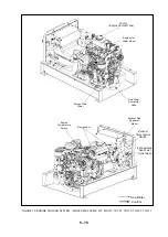
Page 21: ...L FILTER AND SERVICE POINTS MN 305 MS 306 MN 307 MS 307 MG 309 TG 309 OIL DIPSTICK FUEL FILTER OIL FILLER CAP FUEL FILTER FIGURE 10 FUEL FILTER OIL FILTER AND SERVICE POINTS MN 305 MS 306 MN 307 MS 307 MANUAL OIL PUMP FUEL FILTER ...

Page 22: ...SERVICE POINTS MS 312 MS 316 MS 323 MG 314 MG 315 MG 320 MG 323 TG 314 TG 315 TG 320 TG 323 TS 312 TS 315 TS 320 TS 323 OIL FILLING COVER FIGURE 12 FUEL FILTER OIL FILTER AND SERVICE POINTS MS 312 MS 316 MS 323 MG 314 MG 315 MG 320 MG 323 TG 314 TG 315 TG 320 TG 323 TS 312 TS 315 TS 320 TS 323 MANUAL OIL PUMP OPTIONAL ...

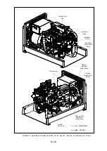
Page 23: ...GURE 13 FUEL FILTER OIL FILTER AND SERVICE POINTS MG 330 MS 330 TG 330 TS 330 MANUAL OIL PUMP OPTIONAL FUEL FILTER FIGURE 14 FUEL FILTER OIL FILTER AND SERVICE POINTS TG 343 TS 343 OIL DRAIN HOSE FUEL FILTER OIL DIPSTICK OIL FILLING COVER FUEL FILTER ...

Page 24: ...ing the first operation of the generator set check the coolant level inside the Engine Coolant Expansion tank and re fill the expansion tank with appropriate coolant up to the FULL level when the engine is cold Engine Coolant Expansion tank is designed to keep coolant level inside the engine fixed during the operation Lack of coolant inside the engine cannot be resolved by filling this tank If the...

Page 25: ...nd ff If the engine continues to stop clean the heat exchanger pipes and covers If there is a freezing danger drain the heat exchanger when the generator set is not operated or stored Cold water may damage the water pipes in the heat exchanger Zinc Anode Apply the zinc anode with gear filling compound on zinc plug and drain the plugs Page 5 1 Table 2 and remove the cover gasket if the old ones are...

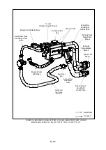
Page 26: ... Pump Inlet Hose Pump of Sea Water Zinc anode Exhaust Gas Seawater Elbow Exhaust Gas Sea Water Outlet Hose Engine Temperature Switch FIGURE 15 ENGINE COOLING SYSTEM MN 305 MS 306 MS 307 MS 310 TS 307 TS 310 TG 307 TG 311 Sea Water Coolant Exhaust Temperature Switch ...

Page 27: ...ler Engine Coolant Tank Engine Hot Water Elbow Sea Water Heat Exchanger Inlet Hose Sea Water Exchanger Outlet Hose Exhaust Gas Sea Water Elbow Exhaust Temperature Switch Siphon Kit Elbow Exhaust Gas Sea Water Outlet Pipe Zinc Anode Coolant Sea Water Exhaust Gas Sea Water Hose Sea Water Inlet Sea Water Inlet Hose to Pump Engine Water Inlet Hose ...

Page 28: ...MG 309 TG 309 MS 307 TS 307 5 12 Coolant Filler Cap Hot Water Elbow Sea Water Pump Sea Water Inlet Hose to Pump Zinc Anode Exhaust Gas Sea Water Elbow Exhaust Gas Sea Water Outlet Hose Coolant Drain Tap Coolant Sea Water Exhaust Temperature Switch ...

Page 29: ... Cooler Engine Coolant Tank Coolant Filler Cap Zinc Anode Sea Water Exchanger Outlet Hose Exhaust Gas Sea Water Elbow Engine Hot Water Elbow Exhaust Gas Sea Water Outlet Sea Water Inlet Sea Water Pump Sea Water Inlet Hose to Pump Exhaust Gas Sea Water Hose Coolant Sea Water Exhaust Temperature Switch ...

Page 30: ...TG 323 TS 312 TS 315 TS 320 TS 323 5 14 Cooler Coolant Filler Cap Thermostat Housing Coolant Drain Tap Sea Water Pump Sea Water Inlet Hose to Pump Sea Water Exchanger Outlet Hose Exhaust Gas Sea Water Elbow Exhaust Temperature Switch Exhaust Gas Sea Water Outlet Hose Zinc Anode Coolant Sea Water ...

Page 31: ...3 TG 314 TG 315 TG 320 TG 323 TS 312 TS 315 TS 320 TS 323 5 15 Sea Water Inlet Opening Zinc Anode Sea Water Pump Siphon Kit Elbow Engine Hot Water Elbow Exhaust Gas Sea Water Elbow Exhaust Temperature Switch Exhaust Gas Sea Water Outlet Opening Coolant Filler Cap Cooler Engine Coolant Tank Coolant Sea Water ...

Page 32: ...Cooler Engine Coolant Tank Coolant Filler Cap Engine Hot Water Elbow Sea Water Pump Sea Water Inlet Hose to Pump Zinc Anode Sea Water Heat Exchanger Outlet Hose Exhaust Temperature Switch Exhaust Gas Seawater Elbow Exhaust Gas Sea Water Outlet Hose Coolant Sea Water ...

Page 33: ...lant Tank Exhaust Gas Sea Water Hose Sea Water Inlet Hose to Pump Engine Hot Water Elbow Coolant Filler Cap Zinc Anode Siphon Kit Elbow Sea Water Exchanger Outlet Hose Exhaust Temperature Switch Sea Water Pump Sea Water Heat Exchanger Outlet Hose Coolant Sea Water Exhaust Gas Seawater out mouth Sea Water Spout ...

Page 34: ... 343 TS 343 5 18 Engine Hot Water Elbow Cooler Engine Coolant Tank Sea Water Inlet Hose to Pump Sea Water Pump Coolant Filler Cap Zinc Anode Sea Water Exchanger Exit Exhaust Temperature Switch Sea Water Exchanger Outlet Exhaust Gas Sea Water Hose Coolant Sea Water ...

Page 35: ...nger 5 Install the new internal gear Lubricate inside of the pump and internal gear with soapy water or silicone lubricant before operating the pump to provide ease of installation first lubrication and better pump intake Do not lubricate the internal gear with grease mineral oil or other petroleum products Because these chemicals may contain materials that may spoil the structure and form of the ...

Page 36: ... Remove the slackness of the belt by tightening the battery charging alternator 4 Remove the battery negative terminal to prevent operation of the engine Replace and check the component according to the following instructions 5 Rotate the alternator a few times to stretch the V belt Adjust the belt tension properly by tightening the adjustment ring bolt and check the tension by applying 10 kg load...

Page 37: ...nt Heat Exchanger under excessive temperature and pressure may spurt hot vapors and cause serious burns 2 Remove the hose clamp connected to the thermostat side with proper tools without damaging the components 3 Remove the outer bolts of the part including the thermostat Remove the thermostat with the sealing gasket 4 Clean the sealing gasket surfaces on the connection points Install new thermost...

Page 38: ...ou are disconnecting the battery cables Use the generator set control panel for troubleshooting any faults or problems Table 3 Always apply the following corrective and preventive measures while troubleshooting Contact authorized service if you still cannot resolve the problem Page 2 1 NOTE Many faults and problems on generator sets may be prevented by periodical maintenances Most frequent problem...

Page 39: ... from connection points Check the connection points to repair properly and remove the leaks V belt driving the engine coolant circulation pump is slackened Adjust the V belt slackness properly adjust the belt sag to 6 8mm Engine coolant circulation pump is faulty Contact an authorized dealership Siphon kit is not working Ensure that the siphon kit is drained and operates properly Sea Water Pump In...

Page 40: ...is slackened Adjust the V belt slackness properly adjust the belt sag to 6 8mm Interference with battery supplied devices may reduce the desired effect of the charge Perform necessary measurements Disable the device when required Starting lamp is turned on Engine cannot be started due to the incapability of the starter Alternator takes too much energy from the engine Turn the circuit breaking fuse...

Page 41: ...ights heaters big A Cs water heaters etc There may be a fault on the fuel system Repair fuel leaks in the fuel system and remove air bubbles remaining in the system There may be air inside the fuel system Bleed the air of fuel system properly Fuel quality may be improper Use fuel with quality conforming with the specifications specified by engine manufacturer Engine operating air is inadequate Pro...

Page 42: ...n Excessive load Short circuit in the electrical installation of the vessel Check the electrical installation Circuit breaker is faulty Replace with a new one Engine is not running PTO takes too much energy from the engine Disable the PTO Inadequate fuel in fuel tank Check whether there is enough fuel to operate the generator in the main fuel tank There may inadequate fuel supply Check for any blo...

Page 43: ...or gives a warning signal There may be excessive carbon monoxide build up inside the vessel Immediately take everyone to open air Ensure proper ventilation Seek medical assistance when required Engine does not stop Stop solenoid is not operating Stop the engine by cutting the fuel off Contact an authorized dealership 6 6 ...

Reviews: