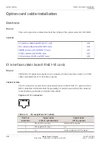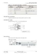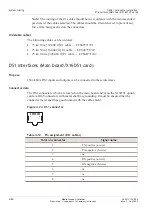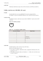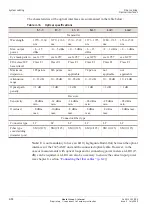
Table 4-18
Optical SFP specifications
(continued)
S1.1
L1.1
L1.2
Overload
–8 dBm max.
–10 dBm max.
–10 dBm max.
Connector/Fiber type
Connector type
LC
LC
LC
Fiber type core/cladding
diameter (µm)
SM (9/125)
SM (9/125)
SM (9/125)
Cable connection
The routing of the fiber away from the equipment should be in accordance with the
specifications for the selected fiber. Take care not to exceed the bending radius when
placing the fiber (nominal minimum 2.54 cm bending radius). Exceeding the
recommended radius may cause distortion and poor signal quality. Strain relieve the
cables to prevent any force from being exerted on the connectors. Clean all connections,
as required, before attaching.
Aggregate interfaces (Main board)
Purpose
There are four aggregate interfaces (located on the main board). Both LP1.1 and LP1.2
can equip an STM-4 SFP or an STM-1 SFP. LP1.3 and LP1.4 can only equip STM-1
SFPs.
Connector data
The aggregate fiber connectors which are located on the main board are equipped with
LC connectors (SFPs necessary).
Cable data
Single Mode (SM) fibers must be used.
Cable connection
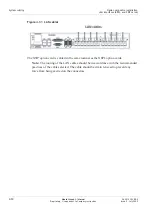
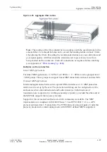
Please connect the aggregate fiber cables as shown in the figure below:
System cabling
Fiber cabling
Optical interfaces (X6STM1 card)
...................................................................................................................................................................................................................................
...................................................................................................................................................................................................................................
4-36
Alcatel-Lucent – Internal
Proprietary – Use pursuant to Company instruction
365-313-103R8.0
Issue 2
July 2009

