Power and ground cable installation
Overview
Purpose
This section provides information about the power and ground cable installation.
Contents
Power interfaces
Before you begin
Before connecting any power cables be sure that all circuit breakers which are located in
the external Battery Distribution and Fuse Bay (BDFB) and/or on a Power Distribution
Panel (PDP) are in the
OFF
position.
Important!
The power cables should be connected later (see section
and testing supply voltage” (p. 5-3)
DC connector data
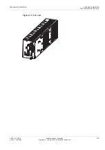
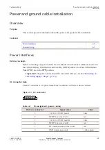
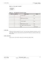
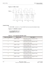
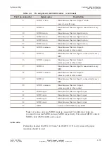
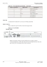
The DC connector is a 6-pin terminal block connector with screw down contacts.
Table 4-1
Pin assignment (power cables)
Point on connector
Signal name
Color
1
–24/–48/–60 VDC, feed A
blue
2
DC RT (return), feed A
red
3
–24/–48/–60 VDC, feed B
blue
4
DC RT (return), feed B
red
5
DC common return for feed A+B
red
6
GD (common ground)
yellow/green
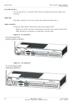
Figure 4-1 DC connector
-A
Ra
-B
Rb
Rab
G
1
6
System cabling
Power and ground cable installation
Overview
...................................................................................................................................................................................................................................
...................................................................................................................................................................................................................................
365-313-103R8.0
Issue 2
July 2009
Alcatel-Lucent – Internal
Proprietary – Use pursuant to Company instruction
4-3

