Fan alarm and LED interface
Purpose
An external alarm equipment can be connected to this interface.
Connector data
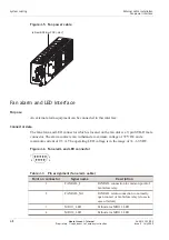
The fan alarm and LED connector which is located on the fan unit is a 9-pin SUB-D male
connector. The alarm contacts can withstand a maximum voltage of 72 VDC and a
maximum current of 0.5 A. The operating LED voltage is in the range of 36...60 VDC.
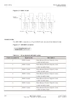
Table 4-3
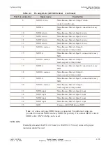
Pin assignment (fan alarm cable)
Point on connector
Signal name
Description
1
FAFAIL_C
FAFAIL connection to common point of
fan failure relay
2
FAFAIL_O
FAFAIL return connection to normally
open contact of fan failure relay (closes in
case of failure)
3
MDO1_LED
Cathode for MDO 1 LED
4
MDO2_LED
Cathode for MDO 2 LED
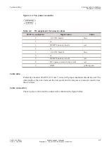
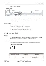
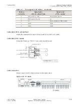
Figure 4-5 Fan power cable
to/from BDFB or PDP (-48 V)
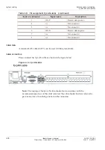
Figure 4-6 Fan alarm and LED connector
1
6
5
9
System cabling
External cable installation
Fan power interface
...................................................................................................................................................................................................................................
...................................................................................................................................................................................................................................
4-8
Alcatel-Lucent – Internal
Proprietary – Use pursuant to Company instruction
365-313-103R8.0
Issue 2
July 2009


