background image

............................................................................................................................................................................................................................................................

Local testing and operating sequence

Tests and Measurements

3-26

 PN 8DG08136CAAA

Issue 1 March 2008

............................................................................................................................................................................................................................................................

Open the SONET loop to check the presence of the TSF alarm on the remote port, as 
described in the following.

Select a remote port. From the pop-up menu, select “Configure Ethernet port.”

 In “Ethernet port Configuration” window, select “Configuration” tag and set “Up” 
in “Admin. Status” field. Click on “OK.”

Select the remote port again, open the pop-up menu and select “Ethernet Port 
Properties.” Open the “Alarms” tag and check the presence of the TSF alarm (red 
square).

Connect the instrument and check that the alarms (LOS and TSF) disappear.

The alarm signalling is also displayed in the CT main window, by a red circle on 
the left of the port.

........................................................................................................................................................

E

N D

  O

F

  S

T E P S

CLI Procedure

........................................................................................................................................................................................................................

1

Cross-connect the GbE port (on PIM1GE) to the SONET port via the multiservice PIM 
(PIMMS) and the Matrix (MT320)

........................................................................................................................................................................................................................

2

By CT create a number of active VC4-xV (x = 7) on PIMMS, as shown in 

Chapter 4

“Unprotected, bi-directional cross-connect: concatenated group (VC4-7V) and STM-N 
port” (p. 4-9)

.

........................................................................................................................................................................................................................

3

Cross-connect the VC4-7V to an SONET port (OC-36), as shown in 

Chapter 4

“Unprotected, bi-directional cross-connect: concatenated group (VC4-7V) and STM-N 
port” (p. 4-9)

.

........................................................................................................................................................................................................................

4

Cross-connect the VC4-7V to one port of the 10 x 1 GbE PIM (PIM1GE), as shown in 

Chapter 4

“Cross-connection between a local and a remote data port” (p. 4-12)

.

........................................................................................................................................................................................................................

5

Start transmitting at 100% of the available bandwidth

Pattern generator / Error Detector setup

Port type

GbE

Auto-negotiation

ON

Summary of Contents for 1850 TSS-320

Page 1: ...Alcatel Lucent 1850 TRANSPORT SERVICE SWITCH 320 TSS 320 RELEASE 2 0 TURN UP AND COMMISSIONING GUIDE PN 8DG08136CAAA MARCH 2008 ISSUE 1 ...

Page 2: ...ful interference to radio communications Operation of this equipment in a residential area is likely to cause harmful interference in which case the user will be required to correct the interference at the expense of the user Security Statement In rare instances unauthorized individuals make connections to the telecommunications network through the use of remote access features In such an event ap...

Page 3: ...roduct xi 1 Safety Introduction 1 2 Safety rules 1 3 2 Initial Turn up and Provisioning Initial turn up sequence instructions 2 2 Startup procedure 2 3 Initial Provisioning 2 7 3 Tests and Measurements Instruments accessories and related documents 3 2 Connection points position 3 5 Local testing and operating sequence 3 9 Point to point measures list and operating sequence 3 59 4 Connections Confi...

Page 4: ...i directional cross connect concatenated group VC4 7V and STM N port 4 9 Cross connection between a local and a remote data port 4 12 Standard procedures to turn the laser OFF then ON 4 14 SFP and XFP modules optical characteristics 4 16 5 1850 TSS 320 Test Report Sheet Modules Equipment acceptance sheet 5 2 A Technical Support GL Glossary ...

Page 5: ...ching test untagged frames 3 36 3 8 Commissioning example 3 39 3 9 Line terminal configuration in DWDM systems 3 40 3 10 ILA configuration in DWDM systems 3 41 3 11 Optical add drop multiplexer ROADM degree 2 in DWDM system 3 42 3 12 Local test in line terminal configuration in DWDM systems 3 42 3 13 Local test in OADM configuration in DWDM systems 3 45 3 14 Link test in DWDM system 3 46 3 15 End ...

Page 6: ... List of figures v i PN 8DG08136CAAA Issue 1 March 2008 ...

Page 7: ...ations and Characteristics 4 1 OC 3 optical characteristics 4 16 4 2 OC 48 optical characteristics 4 16 4 3 OC 48 optical characteristics 4 17 4 4 OC 192 optical characteristics 4 18 5 1850 TSS 320 Test Report Sheet Modules 5 1 Equipment acceptance sheet 5 2 5 2 On Site 1850 TSS 320 Final Test 5 3 5 3 On Site 1850 TSS 320 Final Test SONET SONET Local Measurements 5 4 5 4 On Site 1850 TSS 320 Final...

Page 8: ... List of tables v i i i PN 8DG08136CAAA Issue 1 March 2008 ...

Page 9: ...le for the installation turn up acceptance operations and maintenance of the 1850 TSS 320 How to use this document This manual is divided into several chapters and appendices The first chapter contains safety information and general installation information The other chapters provide instructional steps for personnel needing additional detail or background information This document describes the 1...

Page 10: ...S 320 Installation Guide 8DG08136DAAA 1850 TSS 320 Maintenance and Trouble Clearing Guide 8DG08136EAAA 1850 TSS 320 Craft Terminal Operation Guide 8DG08136FAAA 1850 TSS 320 TL1 Operation Guide 8DG08136GAAA 1850 TSS 320 CLI Operation Details 8DG08136HAAA 1850 TSS 320 Safety Guide Document support Alcatel Lucent provides a referral telephone number for document support Use this number to report erro...

Page 11: ... and packaging waste within specific jurisdictions please contact the Alcatel Lucent Field Services Installation Environmental Health and Safety organization For installations not performed by Alcatel Lucent please contact the Alcatel Lucent Customer Support Center at Technical Support Services Alcatel Lucent Within the United States 1 866 582 3688 prompt 1 From all other countries 1 630 224 4672 ...

Page 12: ...l offer to provide for the collection and treatment of Alcatel Lucent products at the end of their useful life Alcatel Lucent will also offer to provide for the collection and treatment of existing products displaced by Alcatel Lucent equipment For information regarding take back of equipment by Alcatel Lucent or for more information regarding the requirements for recycling disposal of product ple...

Page 13: ... 1 March 2008 1 Safety Overview Purpose This chapter provides important information and safety instructions the for 1850 TSS 320 Release 2 0 equipment Contents This chapter covers these topics Introduction 1 2 Safety rules 1 3 ...

Page 14: ...n table LDT supplied by the link designers The documentation of the tests carried out during the system test phase is provided with the equipment TRS LDT All the measurements necessarily executed to correctly insert the equipment into the network are repeated on site To this concern reference is made to the results of the factory tests carried out on the system Symbols To simplify the description ...

Page 15: ...ctions while the equipment is in service To reduce the risk of damaging the electrostatic sensitive devices it is mandatory to use the elasticized band worn around the wrist and the coiled cord connected to the rack ground when having to touch the equipment All measures must be done at the ODF DDF points ODF Optical Distribution Frame DDF Digital Distribution Frame Inserting the units and modules ...

Page 16: ... Safety rules Safety 1 4 PN 8DG08136CAAA Issue 1 March 2008 ...

Page 17: ...08 2 Initial Turn up and Provisioning Overview Purpose This chapter lists the instructions that must be sequentially carried out as well as additional information Contents This chapter covers these topics Introduction 1 2 Safety rules 1 3 ...

Page 18: ...cumentation Verify any fiber connections to office DDF ODF based on office documentation Verify inter and intra subrack fiber connections as specified in Installation Guide and engineering documentation Verify fiber labeling and routing and inspect for damaged or pinched fibers or fibers that exceed the minimum bend radius Verify all electrical and power cable and ground connections as specified i...

Page 19: ...software configuration and installation Refer to the 8DG08136EAAA Alcatel Lucent 1850 TSS 320 Craft Terminal Operation Guide Note An FTP server program installed and running is mandatory for software download It is also required that any firewalls running on the PC be disabled Software download at the first installation For the 1850 TSS 320 connection points refer to Figure 1 on page 27 To perform...

Page 20: ...able In the following the commands to be entered by the operator in the Hyperterminal connection to the debug port 17 are in bold After typing the command press ENTER d reboot e when the program indicates PRESS CRTL C to stop the boot sequence enter CTRL C f login root g disk init FORMAT HARDDISK RAID to format the hard disk h disk init MOUNT i insert the USB key on which the keyfsimage file have ...

Page 21: ...e NE SW package twice Version IP address Port FTPusern Directory FTPpassword Three types of SW packages are available 1850TSS320M M Multiservice 1850TSS320T T Transport SDH WDM 1850TSS320D D Data h At the end the program give the result of the procedure i e success i key exit it is now possible to remove the USB key j disk init UMOUNT k reboot wait 5 10 minutes for reboot to finish l ifconfig eth1...

Page 22: ...008 e reboot wait 5 10 minutes for reboot to finish f ifconfig eth1 151 98 152 196 to configure the IP address of the ETH1 port of 1850 TSS 320 Proceed to Initial Provisioning It is now possible to start the CT application see the Craft Terminal Operations Guide for additional information ...

Page 23: ...o provision the system See the Craft Terminal Operation Guide for details on provisioning the NE using the Craft Terminal Initial Provisioning Using TL1 a Connect the PC ethernet port to the EC320 ETH LAN port 20 by means of the ethernet cable b Open a telnet session to port 3083 using the IP address provisioned during the Initial Software download Figure 2 1 shows the TL1 setup for Hyperterminal ...

Page 24: ... the appropriate DWDM shelf type ENT EQPT TID SHELF 1 1 PROVISIONEDTYPE ROADM SHELFNUM 1 SHELFROLE MAIN SHELFWDMROLE WDMMASTER IS This example provisions the shelf as a ROADM sets shelf number to 1 sets this shelf as the main shelf and the WDM master shelf and puts it in service This will cause the shelf to reboot Note See the TL1 Operations Guide for syntax options of the ENT EQPT TL1 command g I...

Page 25: ...Initial Provisioning Initial Turn up and Provisioning PN 8DG08136CAAA Issue 1 March 2008 2 9 Figure 2 2 OMD OTS assignment ...

Page 26: ...XC command to enter cross connect from OMD to optical channel ID ENT CRS PXC TID OMDPORT 1 2 1 9600 OTSOCHPORT 1 1 2 9600 ctag This example provisions bidirectional channel 9600 to from the OMD designated as SHELF 1 2 1 to the WR pack in slot 1 1 2 See the 1850 TSS 320 R2 0 TL1 Operations Guide for additional information on other circuit types c Use one of the following commands to provision the c...

Page 27: ...tructions that must be sequentially carried out as well as additional information Contents This chapter covers these topics Instruments accessories and related documents 3 2 Connection points position 3 4 Local measures list and operating sequence 3 8 Point to point measures list and operating sequence 3 56 ...

Page 28: ... 10 Gb Ethernet B Optical power meter Power Meter 1 Capable of taking measurements at 1310 and 1550 nm C Single mode variable optical attenuator VOA 1 Variable attenuator capable of 0 50 dB attenuation at both 1310 and 1550 nm D Digital multimedia 1 E Personal Computer as Craft Terminal 1 See the Craft Terminal Operation Guide F Data Tester 1 Tx rate up to 64 kbit s contra directional CCITT interf...

Page 29: ...r LAN port on PC RS 232 RJ45 connector on EC320 Debugger port 20 O USB key 1 Termination USB connector on EC320 USB interface 19 Minimum 256M P Cables for synchronization 1 Termination Instrument G Frequency Counter Synchronization termination 120 or 75 ohm Q Multi mode single fiber splices 4 Terminations dependent on unit pack ODF connectors power meter and attenuator R Fixed attenuators suggeste...

Page 30: ...nal M1 RJ45 M2 SubD 9PIN Pair Color DATA CARRIER DETECT DCD 1 1 1 White blue ring OUTPUT SERIAL DATA LINE RXD 2 2 Blue INPUT SERIAL DATA LINE TXD 3 3 2 White orange ring DATA TERMINAL READY DTR 4 4 Orange GROUND GND 5 5 3 White green ring DATA SET READY DSR 6 6 Green REQUEST TO SEND RTS 7 8 4 White brown ring CLEAR TO SEND CTS 8 7 Brown Shell Shield ...

Page 31: ...1 5 9 2 5 1 4 1 3 1 8 1 1 5 9 2 5 1 4 1 3 1 1 3 1 3 PSFA PSFB A U XC H A N N ELS STU PA STU PB H O U SEK EEPI N G SH ELFI D R L R A 39 36 35 34 33 32 31 30 29 28 27 26 25 24 23 22 21 20 37 19 18 17 16 15 14 13 12 11 10 9 8 7 6 5 4 3 2 1 R D B G 1 2 1 2 L N K A C T M F D X C O L L N K A C T M F D X C O L L N K A C T D S F D X C O L L N K A C T D S F D X C O L R D B G 1 2 1 2 L N K A C T M F D X C O...

Page 32: ...and 2 Not available in the current release 13 38 EOW Extension 4 Wire Interface RJ45 Not available in the current release 14 38 Phone Jack Not available in the current release 15 1 20 Local Craft Terminal Connection mUSB F Interface 16 1 20 Local Craft Terminal Connection RS232 F Interface 17 1 20 RS2342 on mUSB Debug Connector 18 1 20 USB Interface 19 1 20 10 100 Mbps ETH Debug RJ45 Connector 20 ...

Page 33: ...the 1529 nm 1563 nm range on a 100 GHz grid 10XANY 02 to 09 12 to 19 21 to 28 29 to 36 Data TDM concentrator which aggregates up to ten client signals GE 1 2 4 Fibre Channel OC 3 12 48 SONET OC 3 4 16 SONET PP20G 02 03 21 22 04 05 23 24 06 07 25 26 08 09 27 28 12 13 29 30 14 15 31 32 16 17 33 34 18 19 35 36 20 Gbps optical data card packet processor It doesn t provide optical connections PIM1GE On...

Page 34: ...ptical lines WR8 LDRXA LDRXB 5 9 15 and 19 Receive side OA capable of 9 29dB Gain 16dBm out LDRXA or 13 33dB gain 20dBm out LDRXB LDTXA LDTXB 4 8 14 and 18 Transmit side OA capable of 13 20dB Gain 20dBm out LDTXA or 0dB gain without amplification LDTXB OPS 02 to 09 12 to 19 21 to 28 29 to 36 Used for 1 1 protection and protected optical drop and continue applications 11GBAR 02 to 09 12 to 19 21 to...

Page 35: ...rect operating mode of the equipped units They are detailed in the following paragraphs Free running frequency check Purpose Verify the correct value of the frequency of the oscillator on the MATRIX Test instruments Note See Table 3 1 Instruments p 3 2 Craft Terminal E Frequency Counter G Accessories Note See Table 3 2 Accessories p 3 2 Cable for synchronization P Craft Terminal cable L ...

Page 36: ...Stratum 2 Transit Node Clock Stratum 3E Stratum 3 SONET minimum clock Stratum 4 Do Not Use failed state and Not Assigned Secondary Reference Stratum 1 Synchronized BLOCK DIAGRAM 1850 TSS 320 R AT AB C M m W D BG 6 9 1 5 8 1 15 9 25 14 13 1 8 1 15 9 25 14 13 1 1 3 1 3 PSFA PSFB AUX CHANNELS STUPA STUPB HOUSEKEEPING SHELF ID RL RA 39 36 35 34 33 32 31 30 29 28 27 26 25 24 23 22 21 20 37 19 18 17 16 ...

Page 37: ...ed value of 2048 kHz 4 6 ppm To perform this measure the Squelch T0 T4 must be deactivated green color by selecting Synchronization T4 Configuration in Squelch T0 T4 field set T0 G 813 E N D O F S T E P S TL1 Procedure 1 Connect the outgoing synchronism to the frequency counter Enter ED BITS OUT TID CTAG LINECDE FMT ESFTRANS in order to verify that no reference has been selected for each Timing Re...

Page 38: ...48 kHz 4 6 ppm To perform this measure the Squelch T0 T4 must be deactivated green color by selecting Synchronization T4 Configuration in Squelch T0 T4 field set T0 G 813 SONET ports test Purpose Let through data to check if the ports are properly connected to the ODF Check PTx Check that ALS is working properly Test instruments Note See Table 3 1 Instruments p 3 2 Craft Terminal E Pattern Generat...

Page 39: ...B AUX CHA NNE LS STUP A STUPB HO USE KEE PI NG SHE LFI D RL R A 39 36 35 34 33 32 31 30 29 28 27 26 25 24 23 22 21 20 37 19 18 17 16 15 14 13 12 11 10 9 8 7 6 5 4 3 2 1 R DBG 1 2 1 2 L N K A C T M F D X C O L L N K A C T M F D X C O L L N K A C T D S F D X C O L L N K A C T D S F D X C O L R D BG 1 2 1 2 L N K A C T M F D X C O L L N K A C T M F D X C O L L N K A C T D S F D X C O L L N K A C T D ...

Page 40: ...power meter to the optical port output being tested Check that the optical power is within the range stated on the table in Chapter 4 SFP and XFP modules optical characteristics p 4 16 4 Disconnect the pattern generator from the OC 3 or OC 12 input port Check no power on Power Meter 5 Repeat the test on each optical unit E N D O F S T E P S Bit rate 155 520 kbit s Code interface SFP S 1 1 L 1 1 L ...

Page 41: ...er meter to the optical port output being tested Check that the optical power is within the range stated on the table in Chapter 4 Standard procedures to turn the laser OFF then ON p 4 14 4 Disconnect the pattern generator from the OC 3 or OC 12 input port Check no power on Power Meter 5 Repeat the test on each optical unit E N D O F S T E P S Bit rate 155 520 kbit s Code interface SFP S 1 1 L 1 1...

Page 42: ... power meter to the optical port output being tested Check that the optical power is within the range stated on the table in Chapter 4 SFP and XFP modules optical characteristics p 4 16 4 Disconnect the pattern generator from the OC 3 or OC 12 input port Check no power on power meter 5 Repeat the test on each optical unit E N D O F S T E P S Bit rate 155 520 kbit s Code interface SFP S 1 1 L 1 1 L...

Page 43: ...l port see Chapter 4 Standard procedures to turn the laser OFF then ON p 4 14 Type of protected cross connections OC 3 OC 48 OC 192 See Chapter 4 Bi directional protected cross connection OC 3 OC 12 port and STM n ports p 4 6 6 9 1 5 8 1 15 9 25 14 13 1 8 1 15 9 25 14 13 1 1 3 1 3 PSFA PSFB AUX CHANNELS STUPA STUPB HOUSEKEEPING SHELF ID RL RA 39 36 35 34 33 32 31 30 29 28 27 26 25 24 23 22 21 20 3...

Page 44: ...at the LASER power is null If the ALS Automatic Restart option is enabled check if a power reset is attempted after approximately 0 seconds This condition must last approximately 2 seconds If these conditions do not occur replace the optical unit under test Check if the Tx optical power is null Repeat the test on each optical unit Preset the instrument to transmit a signal based on the type of por...

Page 45: ...ower reset is attempted after approximately 0 seconds This condition must last approximately 2 seconds If these conditions do not occur replace the optical unit under test Check if the Tx optical power is null Repeat the test on each optical unit Preset the instrument to transmit a signal based on the type of port used with the following requirements E N D O F S T E P S CLI Procedures By means of ...

Page 46: ...hen ON p 4 14 Check that the LASER power is null If the ALS Automatic Restart option is enabled check if a power reset is attempted after approximately 0 seconds This condition must last approximately 2 seconds If these conditions do not occur replace the optical unit under test Check if the Tx optical power is null Repeat the test on each optical unit Preset the instrument to transmit a signal ba...

Page 47: ... concatenation group VC4 xV Let through data to check if the ports are properly connected to ODF Alarms detection Test instruments Note See Table 3 1 Instruments p 3 2 Craft Terminal E Pattern Generator Error Detector A x dB fixed attenuator Accessories Note See Table 3 2 Accessories p 3 2 Optical loop K Single mode or multi mode single fiber splices I or Q according to the interface type Craft Te...

Page 48: ...cted bi directional cross connect concatenated group VC4 7V and STM N port p 4 9 6 9 1 5 8 1 1 5 9 2 5 1 4 1 3 1 8 1 1 5 9 2 5 1 4 1 3 1 1 3 1 3 P SFA P SFB AUX CH AN NE LS S TU PA S TU PB H O U SE KE EP I NG SH ELFI D R L RA 3 9 36 35 34 33 32 31 30 29 28 27 2 6 25 24 23 22 21 20 3 7 19 18 17 16 15 14 13 12 11 10 9 8 7 6 5 4 3 2 1 R A T A B C M m W D B G R A T A B C M m W D B G S O U R C E S S T ...

Page 49: ...double click on the board i e r1sr1 board 2 The local and remote Data ports are displayed Select a local port From the pop up menu click on the right button of the mouse select Configure Ethernet port In Ethernet port Configuration window select Configuration tag and set Up in Admin Status field Click on OK Select the port again From the pop up menu click on the right button of the mouse select Et...

Page 50: ... Alarms tag and check the presence of the TSF alarm red square Connect the instrument and check that the alarms LOS and TSF disappear The alarm signalling is also displayed in the CT main window by a red circle on the left of the port E N D O F S T E P S TL1 Procedure 1 Cross connect the GbE port on PIM1GE to the SONET port via the multiservice PIM PIMMS and the Matrix MT320 2 By CT create a numbe...

Page 51: ...he mouse select Configure Ethernet port In Ethernet port Configuration window select Configuration tag and set Up in Admin Status field Click on OK Select the port again From the pop up menu click on the right button of the mouse select Ethernet Port Properties Open the Alarms tag and check the presence of the LOS alarm red square Connect the Pattern Generator Error Detector and check that the LOS...

Page 52: ...alling is also displayed in the CT main window by a red circle on the left of the port E N D O F S T E P S CLI Procedure 1 Cross connect the GbE port on PIM1GE to the SONET port via the multiservice PIM PIMMS and the Matrix MT320 2 By CT create a number of active VC4 xV x 7 on PIMMS as shown in Chapter 4 Unprotected bi directional cross connect concatenated group VC4 7V and STM N port p 4 9 3 Cros...

Page 53: ... Click on OK Select the port again From the pop up menu click on the right button of the mouse select Ethernet Port Properties Open the Alarms tag and check the presence of the LOS alarm red square Connect the Pattern Generator Error Detector and check that the LOS alarm disappears green square and that the on board led related to the GbE port under test is green Open the SONET loop to check the p...

Page 54: ...0 GbE Transport on VC4 xV Check 10 GbE packets transport by means of VC4 xV virtual concatenation Purpose Check if the Virtual concatenated ETS cross connection works properly with limited capacity 7 VC4 of the Virtual concatenation group VC4 xV Let through data to check if the ports are properly connected to ODF Alarms detection Test instruments Note See Table 3 1 Instruments p 3 2 Craft Terminal...

Page 55: ...ect concatenated group VC4 7V and STM N port p 4 9 6 9 1 5 8 1 1 5 9 2 5 1 4 1 3 1 8 1 1 5 9 2 5 1 4 1 3 1 1 3 1 3 PSFA P SFB A U XC H A N N ELS STU PA STU PB H O U SE K EEP I N G SH ELFI D R L R A 39 36 35 34 33 32 31 30 29 28 27 26 25 24 23 22 21 20 37 19 18 17 16 15 14 13 12 11 10 9 8 7 6 5 4 3 2 1 R A T A B C M m W D B G R A T A B C M m W D B G S O U R C E S S T A T U S S O U R C E S S T A T U...

Page 56: ...nagement window double click on the board i e r1sr1 board 2 The local and remote data ports are displayed Select a local port From the pop up menu click on the right button of the mouse select Configure Ethernet port In Ethernet port Configuration window select Configuration tag and set Up in Admin Status field Click on OK Select the port again From the pop up menu click on the right button of the...

Page 57: ...larms tag and check the presence of the TSF alarm red square Connect the instrument and check that the alarms LOS and TSF disappear The alarm signalling is also displayed in the CT main window by a red circle on the left of the port E N D O F S T E P S TL1 Procedure 1 Cross connect the 10 GbE port on PIM10GE to the SONET OC 192 port via the multiservice PIM PIMMS and the Matrix MT320 2 By CT creat...

Page 58: ...he right button of the mouse select Configure Ethernet port In Ethernet port Configuration window select Configuration tag and set Up in Admin Status field Click on OK Select the port again From the pop up menu click on the right button of the mouse select Ethernet Port Properties Open the Alarms tag and check the presence of the LOS alarm red square Connect the Pattern Generator Error Detector an...

Page 59: ...larm signalling is also displayed in the CT main window by a red circle on the left of the port E N D O F S T E P S CLI Procedure 1 Cross connect the 10 GbE port on PIM10GE to the SONET OC 192 port via the multiservice PIM PIMMS and the Matrix MT320 2 By CT create a number of active VC4 xV x 1 to 64 7 VC4 are used in current example VC4 7V on PIMMS as shown in Chapter 4 Unprotected bi directional ...

Page 60: ...OK Select the port again From the pop up menu click on the right button of the mouse select Ethernet Port Properties Open the Alarms tag and check the presence of the LOS alarm red square Connect the pattern generator error detector and check that the LOS alarm disappears green square and that the on board LED related to the 10 GbE port under test is green Open the SONET loop to check the presence...

Page 61: ... alarm signaling is also displayed in the CT main window by a red circle on the left of the port E N D O F S T E P S Q Bridge VLAN switching test tagged frames Purpose Check that the Q Bridge is able to transport tagged traffic among the ports set Test instruments Note See Table 3 1 Instruments p 3 2 Craft Terminal E Pattern Generator Error Detector A x dB fixed attenuator Accessories Note See Tab...

Page 62: ... of the mouse select Substitute Client Layer and then ETB Layer In the following window click Yes to confirm 6 9 1 5 8 1 1 5 9 2 5 1 4 1 3 1 8 1 1 5 9 2 5 1 4 1 3 1 1 3 1 3 PSFA PSFB A U XCH AN N ELS STUPA STU PB HO U SEK EEPI N G SH ELFI D RL R A 39 36 35 34 33 32 31 30 29 28 27 26 25 24 23 22 21 20 37 19 18 17 16 15 14 13 12 11 10 9 8 7 6 5 4 3 2 1 R A T A B C M m W D B G R A T A B C M m W D B G...

Page 63: ...figuration tag and set Up in Admin Status field Click on OK In the 1850 TSS Service Management window select the node on top of the list open the pop up menu and select VLAN Registration In the VLAN Registration List window insert the value of the VLAN is being created i e 10 in the New VLAN field and click on Create In the VLAN Registration Management window select the local port in Available Net...

Page 64: ...ct document released by a Project Manager and in the Link Description Table LDT The procedure is divided in two parts Local test Link test The node local test must be performed first The link tests can be carried out after local tests on all nodes Pattern generator Error Detector setup Port type GbE Auto negotiation ON Frame length 1518 bytes Bandwidth 100 VLAN TAG Value set via CT i e 10 Optical ...

Page 65: ...wing 1 The operator A performs the local tests on the Terminal A The operator B performs the local tests on ROADM ILA A B The operators jointly perform the span I attenuation test 2 The operators perform the same operations carried out in STEP 1 on Terminal B and SPAN II E N D O F S T E P S At the end of link tests it is necessary to come back on all nodes for all the link test presettings removal...

Page 66: ...anned Optical Mux Demux OMD44 up to 44 channel Figure 3 9 Line terminal configuration in DWDM systems In an ILA in line amplifier configuration the 1850 TSS 320 connects to an optical fibre DWDM line in each direction Line Drivers LDRXA and LDRXB with the OSC The ILA consists of two optical double stage ILAs providing bi directional wide band amplification in order to boost the optical power of th...

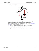
Page 67: ...e or more wavelengths to from the aggregate signal in more than one direction The schematic representation of the ROADM configuration is shown in Figure 3 11 on p 3 42 The ROADM consists of the following Line drivers LDRX_ and LDTX_ with the OSC for each side of the line Wavelength router WR4 or WR8 one for each direction Optical Mux Demux OMD44 up to 44 channels one for each direction LDRXB LDRXA...

Page 68: ... 16 15 14 13 12 11 10 9 8 7 6 5 4 3 2 1 R A T A B C M m W D B G R A T A B C M m W D B G S O U R C E S S T A T U S S O U R C E S S T A T U S R D B G 1 2 1 2 L NK A CT M F DX C OL L NK A CT M F DX C OL L NK A CT D S F DX C OL L NK A CT D S F DX C OL R D B G 1 2 1 2 L N K A C T M F D X C O L L N K A C T M F D X C O L L N K A C T D S F D X C O L L N K A C T D S F D X C O L E L Error Detector Pattern G...

Page 69: ... MUX output and OMD DEMUX input the VOA value must be equal to the total span loss budget 4 Check the output power of each DWDM port by means of the Power Meter refer to Chapter 4 SFP and XFP modules optical characteristics p 4 16 for power values Then connect each fiber to the related XFP Transmitter and disconnect the other end of the same fiber from each MUX input 5 Check that the insertion los...

Page 70: ...e 10 Connect each fiber to the related DEMUX output then disconnect the other end from each DWDM XFP Rx side Check the following The insertion loss of each fiber is 0 1 dB For each port the received power is in the supported optical range refer to Chapter 4 SFP and XFP modules optical characteristics p 4 16 11 Connect each fiber to the related port XFP Rx side 12 Test the BER at a given bit rate c...

Page 71: ...W DBG SOU R CES STATU S SOU R CES STATU S R DBG 1 2 1 2 LNK ACT M FDX COL LNK ACT M FDX COL LNK ACT DS FDX COL LNK ACT DS FDX COL R DBG 1 2 1 2 LNK ACT M FDX COL LNK ACT M FDX COL LNK ACT DS FDX COL LNK ACT DS FDX COL E L Error Detector Pattern Generator I Q or A BLOCK DIAGRAM 1850 TSS 320 Note All the intra shelf connections aren t shown VOA Pattern Generator Error Detector OMDINV RS2 32 SIG IN S...

Page 72: ...ase refer to the project manager Station B PRX check disconnect the fiber from the OMDX B Line signal input connect it to the Power Meter and verify the compliance with the LDT Reconnect the fiber Station A PRX check disconnect the fiber from the OMDX A Line signal input connect it to the Power Meter and verify the compliance with the LDT Reconnect the fiber c Span 2 check Station B PRX check disc...

Page 73: ...ics p 4 16 On ODF perform a daisy chain in station A connecting CH1 client output to CH2 client input Check that the CH2 client output power Rx value on the instrument is OK Connect the CH2 client output to the pattern generator error detector input and start the stability test at a given bit rate check no errors Figure 3 15 End to end stability test example in DWDM system e After having checked a...

Page 74: ...re Cross connect the tributary port and the line port as reported on the table Performs the test using two different line OC 36 OC 192 ports per each tributary OC 3 port a Check that no errors are read on the error detector b Open one of the Optical loop present on the ODF c Check after a transient condition that no errors are read by the error detector Type of protected cross connections See Sect...

Page 75: ...e L Test Bench Figure 3 16 Matrix CRU EPS protection check Note The figure can change depending on the type of tributary port and on the line port selected For the 1850 TSS 320 shelf configuration refer to Figure 3 5 on p 3 22 Procedure Perform the same cross connection used for the previous SNCP protection test a Preset the instrument to transmit a signal with the following requirements b Check t...

Page 76: ...nchronism priority and holdover Note Connect the instrument to pins 5 RXP and 9 RXN if SUB D 9 pole connector is used R A T A B C M m W D B G 6 9 1 5 8 1 1 5 9 2 5 1 4 1 3 1 8 1 1 5 9 2 5 1 4 1 3 1 1 3 1 3 PSFA PSFB A UXC H A N NELS STU PA STU PB H OU SEK EEPI N G SH ELFI D R L R A 39 36 35 34 33 32 31 30 29 28 27 26 25 24 23 22 21 20 37 19 18 17 16 15 14 13 12 11 10 9 8 7 6 5 4 3 2 1 R D BG 1 2 1...

Page 77: ...cedure 5 Select the physical SPI PPI board termination point value rack subrack board port The example given in the following assumes the presence of two reference clocks Clock derived from a STM n port example r1srsl34 port 1 OpS External clock 1 5 MHz 2 MHzT3 A or B from the power supply PSF320 board A or B 6 Select the first of the above listed reference clocks and give Priority 1 Synchronizati...

Page 78: ...or PPI ports are presented Select one and click on OK c In Input Quality Configuration field select one of the listed options then select the Priority and click on OK The selected port appears in the Synchronization view 2 The following is the CT procedure to set the timing reference from a 2 MHz external clock a Click twice on Rack Subrack b Select the PSF320 board Then in the TP Search Criteria ...

Page 79: ...k Note Check for alarms also on the EC320 panel see 4 10 on page 98 LAMP BLOCK R A T A B C M m W D B G 6 9 1 5 8 1 1 5 9 2 5 1 4 1 3 1 8 1 1 5 9 2 5 1 4 1 3 1 1 3 1 3 P SFA P SFB A UXC H AN NELS S TUPA STU PB H O US EKE E PI N G SH E LFI D RL R A 39 36 3 5 34 33 32 31 30 29 28 27 26 25 24 23 22 21 2 0 37 19 1 8 17 16 15 14 13 12 11 1 0 9 8 7 6 5 4 3 2 1 R DB G 1 2 1 2 L N K A C T M F D X C O L L N...

Page 80: ... up 2 lights OFF Verify that the NURG indication at the top of the rack rack lamps lights ON EML USM Double click on the PSF320 in slot 39 Verify that the BF alarm turns ON d Switch ON breaker B e Switch OFF the step up A Verify that the green LED on the step up 1 turns OFF Verify that the NURG indication at the top of the rack rack lamps lights ON EML USM Double click on the PSF320 in slot 37 Ver...

Page 81: ...pment internal service power supplies 6 7 RA_NURG Not urgent alarm 8 9 RA_ORC Fault or loss of one equipment internal service power supply 10 11 RA_INT Internal alarm 12 13 RA_IND Indeterminate alarm 14 15 RA_REF Voltage reference of remote alarms case GND Electrical ground Case Pin Signals Description URG Extract one unit in service Moreover this procedure turns ON the major M LED on EC320 The ma...

Page 82: ...e Lamp block between the N and P contacts of the couple of HK OUT signal to be tested i e between HK_OUTN_1 and HK_OUTP_1 c Select the HK_OUT to be tested and then from the pop up menu select Configuration and set ON the External state field click on OK d Verify that the related alarm is present by observing that the lamp block turns ON the alarm is also raised on the CT Table 3 8 Housekeeping con...

Page 83: ...nvolved FAN Verify that the RUM alarm turns ON b Repeat the procedure on the other FAN 17 HK_IN3 3 Input 18 HK_IN4 4 Input 19 HK_IN5 5 Input 20 HK_IN6 6 Input 21 HK_IN7 7 Input 22 HK_IN8 8 Input 23 24 HK_REF Voltage reference of input housekeeping 25 case GND Electrical ground Case Pin Signals Description 6 9 1 5 8 1 1 5 9 2 5 1 4 1 3 1 8 1 1 5 9 2 5 1 4 1 3 1 1 3 1 3 PSFA PSFB A U XC H AN N ELS S...

Page 84: ...t Terminal E Accessories see Table 3 2 Accessories p 3 2 Cable for Craft Terminal L The following operations must be carried out at the end of the STAND ALONE tests Disconnect all the cross connections made on the equipment during the test operation phase If set down in the executive design configure the following The LAPD protocol based on the line interfaces implemented The IP address The NE loc...

Page 85: ...checks have been made then the failure is due to external causes If local checks have not been executed proceed as instructed in para 3 3 from page 32 In this section the following are detailed Rx optical line port power check Optical line port link margin Point to point error monitoring check Rx Optical line port power check Purpose Verify the optical power of the signal received from the remote ...

Page 86: ... the CT turn on the laser see para 4 6 on page 86 Station A 3 Wait for 180 seconds and then check that the Rx optical power complies with the expected value Note Rx power must be calculated on plant data PTx Theoretical line attenuation based on customer data 4 Repeat the check on the other port with Line port function E N D O F S T E P S 1850TSS 1850TSS ODF ODF RADIOMETER STM N STM N port port St...

Page 87: ...argin between the Rx optical power in normal line condition and the minimum received optical power by introducing line attenuation related to fixed bit error rate Test instruments see Table 3 1 Instruments p 3 2 Craft Terminal E Power Meter B Variable optical attenuator C Pattern Generator Error Detector A Accessories see Table 3 2 Accessories p 3 2 Optical loop K ...

Page 88: ... the ODF 2 Connect the Rx optical line cable to a variable optical attenuator with attenuation equal to zero connect the other side of the variable optical attenuator to the ODF 3 Preset the instrument according to the port type under test and send a fixed PRBS sequence STATION B 4 On the ODF make a loop on the STM N concerned with point to point connection 1850TSS ODF Station A Station B VARIABLE...

Page 89: ...the optical cable from the STM n input port point A in Figure 28 and connect it to the power meter input 10 Margin level must be minimum 4 dB better than the values reported in para 4 7 on page 87 11 Turn on the laser through the CT see para 4 6 on page 86 12 Wait for 180 sec and then read the Rx optical power The difference between the Rx optical power see Rx Optical line port power check p 3 59 ...

Page 90: ... instruments see Table 3 1 Instruments p 3 2 Pattern Generator Error Detector A Accessories see Table 3 2 Accessories p 3 2 Optical loop K Test Bench Procedure STATION A 1 Connect the Pattern Generator output to the 1850 TSS 320 port input and the pattern generator input to the 1850 TSS 320 port output all the connection must be made on the ODF 1850TSS ODF Station A Station B 1850TSS STM N STM N O...

Page 91: ... 320 port concerned with the point to point connection STATION A 3 Set the pattern generator according to the 1850 TSS 320 port characteristics and send a fixed PRBS sequence 4 After a certain period of time check that no errors are read on the error detector 5 Repeat the check on the other port with the 1850 TSS 320 line port function E N D O F S T E P S ...

Page 92: ...ctor A Accessories see Table 3 1 Instruments p 3 2 Optical loop K Test Bench Procedure STATION A 1 Connect the pattern generator output to the 1850 TSS 320 port input and the Pattern Generator input to the 1850 TSS 320 port output all the connection must be made on the ODF STATION B 2 On the ODF loop the 1850 TSS 320 port concerned with the point to point connection 1850TSS ODF Station A Station B...

Page 93: ...8 3 67 STATION A 3 Set the pattern generator according to the 1850 TSS 320 port characteristics and send a fixed PRBS sequence 4 After a certain period of time check that no errors are read on the error detector 5 Repeat the check on the other port with the 1850 TSS 320 line port function E N D O F S T E P S ...

Page 94: ... Point to point measures list and operating sequence Tests and Measurements 3 68 PN 8DG08136CAAA Issue 1 March 2008 ...

Page 95: ...s chapter covers these topics STN n cross connection Matrix looped STM n 4 2 Bi directional protected unstructured cross connection OC 3 and OC 3 port 4 4 Bi directional protected cross connection OC 3 OC 12 port and STM n ports 4 6 Unprotected bi directional cross connect Concatenated group VC4 7V and STM N port 4 9 Cross connection between a local and a remote data port 4 12 Standard procedures ...

Page 96: ... 1 Click on Create The Main Cross Connection window is displayed 2 Select Unidirectional in the Type field 3 Click on Choose input A Search for Cross connection input window is displayed on the Equipment window 4 Double click on Rack 1 and SR320 1 5 Select the board in Slot n In the TP Search Criteria field select AU4 VC4 in the Class field 6 Click on Search The N AU4 will appear under the relevan...

Page 97: ...The Search for cross connection output window will be displayed 9 Repeat the procedure above described for the Input field selecting the same TP 10 Check that the loop symbol is active on the CC Topology box 11 Select OK 12 To check the performed connections select Configuration Cross connection Cross connection Management and click on Search All the cross connections made will be displayed 13 To ...

Page 98: ... the existing connection by clicking on the line and then click on Delete 1 Click on Create in the Cross connection Management window a new window called Main Cross Connection is opened 2 Select the correct value in the fields Type bi directional and Protection protected 3 Click on Select relevant to the Input field a new window called TP search is opened 4 On the Equipment field click twice on Ra...

Page 99: ...evant to the two ports of the selected SLOT are displayed 8 Select the AU4 port m and click on OK the TP search window is closed 9 Click on Select relevant to the PROT INPUT field of the Main Cross Connection window a new window called TP search is opened 10 Select the AU4 port n and click on OK 11 Click on Select relevant to the Output field of the main cross connection window 12 Select the slot ...

Page 100: ...Connection Management window click on Create button a new window called Main Cross Connection is opened 2 Select the correct value in the Type bi directional and Protection protected fields 3 Click on Choose related to the Input field the Search for Cross Connection Input window is opened 4 On the Equipment field click twice on Rack Rack1 and then on Subrack S320 1 5 On the Equipment field select ...

Page 101: ...ion Protection is opened 10 On the Equipment field select the STM N B board i e OC 48 64 in slot n 11 In the Search Criteria field select AU4 VC4 in Class field 12 Click on Search all the available TPs are displayed in the Termination points field i e up to 16 or 64 TPs for the port B if OC 48 or OC 192 board 13 Select the AU4 and click on OK the Search for Cross Connection Protection window is cl...

Page 102: ...d click on OK the Search for Cross Connection Output window is closed 19 In the Main Cross Connection window click on OK 20 Click on Search in the Cross Connection Management window to see all cross connections performed 21 Check that the symbol of the bidirectional protected cross connection is present the main is a dashed line the protecting is a dotted line E N D O F S T E P S ...

Page 103: ...o have a GbE stream and up to 64 VC4s may be concatenated to have a 10 GbE stream Then click on the Create Change button 3 In Data Port Configuration window click on LCAS Cfg Then click on Enable and Apply 4 To activate TPs click on Ctrl Path Act In the Control Path Activation window select the number of TPs to be active 7 and click on Apply E N D O F S T E P S All TPs are now active and it will b...

Page 104: ...press OK 8 The Main Cross Connection window will be displayed The selected VC4 is inserted in the input box This now has to be selected as the Output TP of the cross connection 9 Click on Choose to select the output TP of the cross connection In Search for Cross connection input window double click on Rack and Subrack S320 1 10 Select the STM N board 4P2G5SO or 1P10GSO In the TP Search Criteria fi...

Page 105: ...all the other six 6 virtual concatenated TPs 15 To check the connections made access Configuration Cross connection Management and click on Search All the connections made will be displayed 16 To delete a connection click on the Cross Connections List line and select Delete To delete a cross connection it is mandatory to have previously deactivated the virtual concatenation VC4 xV E N D O F S T E ...

Page 106: ...board 2 The local and remote data ports are displayed 3 Select a local port From the pop up menu click on the right button of the mouse select Configure Ethernet port 4 In the Ethernet port Configuration window select the Configuration tag and set Up in Admin Status field Click on OK 5 In the Ethernet port Configuration window for GbE ports only select the MAU tag and set Admin Status Enabled in A...

Page 107: ...t Egress by clicking on the relevant square The Filtered search window appears 11 In the Ethernet Port tag click on Search 12 Select the Remote port involved and click on Apply 13 In Port Egress field of the Create ETS XC One Step window the selected remote port is displayed 14 The Connection type is Bidirectional not selectable click on Apply 15 In the History field the performed Cross Connection...

Page 108: ... the SPI block d Select port Physical media ALS Management e Set ALS function Laser Forced OFF and then click on Apply 2 Check if the laser is OFF a Check in the message area port view that the message ALS current state in test is present 3 Set the test bench a Disconnect the optical jumper b Connect the optical device power meter or optical attenuator to carry out the test 4 Turn ON the laser Fro...

Page 109: ...w that the message ALS current state inactive is present 6 ALS enable From EML USM select the board and click twice a Select the port b Select the module c Select the SPI block d Select port physical media ALS Management e Set ALS function ALS Enabled and click on Apply 7 Check ALS status a Check in the message area port view that the message ALS current state active is present E N D O F S T E P S...

Page 110: ...llowed bit rates 155 520 155 520 155 520 Mbps Min extinction ratio dB 8 2 10 10 dB Spectr al width Max 20dB bandwidth nm NA 1 1 nm Max RMS width nm 7 7 3 NA nm Minimum SMSR NA 30 if DFB laser 30 Max chromatic dispersion 100 100 250 250 1900 ps nm Min sensitivity BER 1E 10 28 34 34 dBm Min overload 8 10 10 dBm Max optical path penalty 1 1 1 dB Max receiver reflectance 14 14 25 dB Optical connector ...

Page 111: ...8 18 27 28 dBm Min overload 3 0 8 8 dBm Max optical path penalty 1 1 1 2 dB Max receiver reflectance 27 27 27 27 dB Optical connector Tx Rx Fibre type LC SMF LC SMF Acronym interface type SI 161 I 16 1 SS 161 S 16 1 SL 161 L 16 1 SL 162 L 16 2 OC 48 SFP Module Type I 16 1 S 16 1 L 16 1 L 16 2 OC 48 SFP Module Type S 16 1 Multirate Multiformat Unit OC 48 SFP module type S 16 1 Multirate Multiformat...

Page 112: ...SS 161AR S 16 1 multirate OC 48 SFP Module Type S 16 1 Multirate Multiformat Unit OC 192 XFP Module Type S 64 2b I 64 1 P1L1 2D2 Unit Addressed wavelength 1530 1565 1290 1330 1530 1565 nm Min launched power 1 6 0 dBm Max launched power 2 1 4 dBm Allowed bit rates 9 95 10 3125 10 709 9 95 10 3125 10 709 Gbps Min extinction ratio dB 8 2 6 9 dB Spectral width Max 20 dB bandwidth nm 0 25 1 0 25 nm Min...

Page 113: ...e 1 March 2008 4 19 DWDM Optical Characteristics Refer to the Alcatel Lucent 1850 TSS 320 Release 2 0 Product Information Guide for Optical unit interface characteristics Acronym XS 642 XI 641 XP1L12D2 Interface type S 64 2b 10GBASE E I 64 1 10GBASE L P1L1 2D2 OC 192 XFP Module Type S 64 2b I 64 1 P1L1 2D2 Unit ...

Page 114: ... SFP and XFP modules optical characteristics Connections Configurations and Characteristics 4 20 PN 8DG08136CAAA Issue 1 March 2008 ...

Page 115: ...ue 1 March 2008 5 1850 TSS 320 Test Report Sheet Modules Overview Purpose This chapter provides detailed test report sheet modules for the 1850 TSS 320 Contents This chapter covers these topics Equipment acceptance sheet 5 2 ...

Page 116: ...on Addresses AFI IDI VER AUTH RES DOM AREA Local SYSTEM ID ETHERNET ADDRESS IP ADDRESS FINAL TESTING RESULT OK OK Note __________________________________________________ __________________________________________________ __________________________________________________ __________________________________________________ __________________________________________________ __________________________...

Page 117: ...L TEST Units Types Serial Numbers SHELF SERIAL NUMBER SLOT 1 SLOT 2 SLOT 3 SLOT 4 SLOT 5 SLOT 6 SLOT 7 SLOT 8 SLOT 9 SLOT 10 SLOT 11 SLOT 12 SLOT 13 SLOT 14 SLOT 15 SLOT 16 SLOT 17 SLOT 18 SLOT 19 SLOT 20 SLOT 21 SLOT 22 SLOT 23 SLOT 24 SLOT 25 SLOT 26 SLOT 27 SLOT 28 SLOT 29 SLOT 30 SLOT 31 SLOT 32 SLOT 33 SLOT 34 SLOT 35 SLOT 36 SLOT 37 SLOT 38 SLOT 39 SLOT 40 SLOT 41 ...

Page 118: ...ree data transit 0 errors Errors PTx power test 3 See SFP and XFP modules optical characteristics p 4 16 dBm A L S check Check Test error free data transit 0 errors Errors PTx power test 4 See SFP and XFP modules optical characteristics p 4 16 dBm A L S check Check Test error free data transit 0 errors Errors PTx power test 5 See SFP and XFP modules optical characteristics p 4 16 dBm A L S check C...

Page 119: ... Errors Alarms check 7 Check Test error free data transit 0 errors Errors Alarms check 8 Check Test error free data transit 0 errors Errors Alarms check 9 Check Test error free data transit 0 errors Errors Alarms check 10 Check Test error free data transit 0 errors Errors Alarms check 1 Check Test error free data transit 0 errors Errors Alarms check 2 Check Test error free data transit 0 errors Er...

Page 120: ...al characteristics p 4 16 dBm PTx power test on DWDM XFP output 3 See SFP and XFP modules optical characteristics p 4 16 dBm PTx power test on DWDM XFP output 4 See SFP and XFP modules optical characteristics p 4 16 dBm PTx power test on DWDM XFP output 5 See SFP and XFP modules optical characteristics p 4 16 dBm PTx power test on DWDM XFP output 6 See SFP and XFP modules optical characteristics p...

Page 121: ... and XFP modules optical characteristics p 4 16 dBm PRx power test on DWDM XFP input 2 See SFP and XFP modules optical characteristics p 4 16 dBm PRx power test on DWDM XFP input 3 See SFP and XFP modules optical characteristics p 4 16 dBm PRx power test on DWDM XFP input 4 See SFP and XFP modules optical characteristics p 4 16 dBm PRx power test on DWDM XFP input 5 See SFP and XFP modules optical...

Page 122: ...rix units N 0 errors Errors SNCP protection check Line posts Check Matrix CRU EPS protections check Check Synchronism priority and Holdover Check Alarm check if connected Primary power supply alarms check Check ON SITE MULTISERVICE NODE FINAL TEST LOCAL MEASUREMENTS Measure Expected Value and Tolerance Measured Value Unit Housekeeping alarms check HK IN 1 check HK IN 2 check HK IN 3 check HK IN 4 ...

Page 123: ...ne attenuation based on customer data dBm Rx optical line port power check PORT N TYPE Expected value Remote PTx Theoretical line attenuation based on customer data dBm Optical line port link margin PORT N TYPE Margin level must be min 4 dB better than the values reported in SFP and XFP modules optical characteristics p 4 16 dBm Optical line port link margin PORT N TYPE Margin level must be min 4 ...

Page 124: ... Equipment acceptance sheet 1850 TSS 320 Test Report Sheet Modules 5 10 PN 8DG08136CAAA Issue 1 March 2008 ...

Page 125: ... This chapter provides important technical assistance information for the 1850 TSS 320 Contents This appendix contains the following sections Technical assistance A 2 Accessing and navigating the On Line Customer Support OLCS web site A 7 Other technical support services A 13 ...

Page 126: ...ort Services are available 24 hours a day 7 days a week For additional information regarding Alcatel Lucent Worldwide Services refer to the Alcatel Lucent web site at http www alcatel lucent com solutions Select the appropriate category Service Providers Enterprise Note Use the appropriate steps below for the above categories Service Providers 1 Select Service Providers 2 Select Services 3 Select ...

Page 127: ...l Lucent Welcome Center operator can direct the request to engineers that are highly trained and skilled in resolving issues involving Alcatel Lucent products Technical assistance is available 24 hours a day 7 days a week On line customer support Overview On Line Customer Support OLCS is the Customer Support web site for our customers technical support needs This customer web access tool provides ...

Page 128: ...ers can choose a method for receiving updates email text messaging messages or none Users can choose when updates are wanted when the state of the AR changes any update to the investigation field occurs or any time any text field is modified Users can log into the OLCS web site and view ARs 24 hours a day 7 days a week Data Drop Box The Data Drop Box feature allows Alcatel Lucent support technicia...

Page 129: ...h are technical documents that explain the operation of a particular part of the system The following documents are available in this section Change Notice CN Ethernet Management Guide Method of Procedure MOP Planning Guide Service Assurance Guide Engineering Change Procedure ECP Feature Contents Operations Interworking OI Guide Screen Help White Papers These documents will vary from product to pr...

Page 130: ...ce or preventive nature Alcatel Lucent Alerts contain detailed text descriptions and urgency of Alcatel Lucent product issues that need to be quickly communicated to customers after the deployment of a release or product Product Change Notices The Product Change Notices PCN area provides information on hardware changes for a product There is a selection of choices to help you search for Change Not...

Page 131: ...rmation is sent within 2 business days The following steps tell you how to register for a login 1 Select Register Here on the top right just below the Login and Password boxes of the Online Customer Support https support lucent com portal olcsHome do web site 2 Follow this registration process Select the role and accept the terms of use Provide a business identification and enter in all of the req...

Page 132: ...ime The changes take effect immediately There are two methods to find product information Click My Products to choose a product or click Documentation or Downloads to display a complete product listing When the full product list is displayed use the alphabetic listing default or the category list whichever you prefer Once a product is selected a Product Summary Page is displayed which describes al...

Page 133: ...are both legacy tools The new tools Alcatel Lucent Alerts and Ask AL Knowledgebase are discussed in other sections of this document When you select CARES a general web page displays From that page a particular function can be selected from the left column To provide more information on the selected tool select More from the center column ARs can be viewed using Find an AR or Advanced query created...

Page 134: ...on Center CIC web site or to another OLCS webpage that contains the product documentation Within the Documentation and Downloads area the Technical Notes link brings you to a web page which contains documents that are not release specific and are technical in nature Also within the Documentation and Downloads area the Release Information link brings you to a Library of Release Notes web page that ...

Page 135: ... allows you to modify the Urgency Type and or Products selected Cancel Subscription will stop future Alcatel Lucent Alerts email messages Product Change Notices PCNs You can access Product Change Notices PCNs from the left column on the Customer Support home page unless this view has been changed from the Technical Support section in the center of the page or from the My Bookmarks section if PCNs ...

Page 136: ... network element security features Setup and understand interworking between Alcatel Lucent network elements Perform provisioning operations and remote trouble shooting using CIT EMS and TL1 interfaces Analyze Performance Monitoring Data Understand alarm handling alarm management Provision and understand system synchronization techniques Provision and understand protection schemes BLSR UPSR 1 1 AP...

Page 137: ...p To enroll in the training course Within the United States Visit https training lucent com Call 1 888 582 3688 Prompt 2 Outside the continental United States Visit https training lucent com Contact your in country training representative Call 1 407 767 2798 Fax 1 407 767 2677 Enter Advanced Workshops in the search menu and click Go Choose which Advanced Maintenance Workshop you d like to register...

Page 138: ... Other technical support services Technical Support A 14 PN 8DG08136CAAA Issue 1 March 2008 ...

Page 139: ...ny character Numerics 5E XC Applications that provide the capacity and converged networking capabilities that exisitng networks need to implement Accelerate Voice over IP solutions to rapidly deliver next generation services that enterprises and consumers want A API Application Programming Interface ...

Page 140: ... Glossary GL 2 PN 8DG08136CAAA Issue 1 March 2008 ...

Reviews: