............................................................................................................................................................................................................................................................
Local testing and operating sequence
Tests and Measurements
3-52
PN 8DG08136CAAA
Issue 1 March 2008
............................................................................................................................................................................................................................................................
........................................................................................................................................................................................................................
10
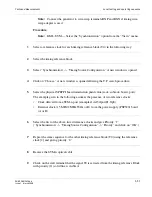
Check on the craft terminal that the signal T0 is derived from the “Int. Oscillator G.813"
timing reference block” (full line is visible) and that hold-over is written.
........................................................................................................................................................................................................................
11
The hold-over state is possible only if the other reference clock has been present for at
least 30 minutes.
1. The following is the CT procedure to set the clock derived from a STM-n port:
a. Click twice on rack/subrack
b. Select the STM-n board. Then in the “TP Search Criteria” section, select “OPS” or
“PPI” in the “Class” field and click on “Search.” The “OPS” or “PPI” ports are
presented. Select one and click on “OK.”
c. In “Input Quality Configuration” field, select one of the listed options, then select
the “Priority” and click on “OK.”
The selected port appears in the “Synchronization” view.
2. The following is the CT procedure to set the timing reference from a 2-MHz external
clock:
a. Click twice on Rack/Subrack
b. Select the PSF320 board. Then, in the “TP Search Criteria” section, select
“Ignore” in the “Class” field, and click on “search.” The input (T3) and output (T4)
timing references are presented.
c. Select “T3” (A or B, according to the PSF320 board selected) and click on “OK.”
d. The selected “T3” timing reference is presented in the “Timing Source
Configuration” window.
e. In “Input Quality Configuration” field, select one of the listed options, then select
the “Priority” and click on “OK.”
........................................................................................................................................................
E
N D
O
F
S
T E P S
Summary of Contents for 1850 TSS-320
Page 6: ... List of figures v i PN 8DG08136CAAA Issue 1 March 2008 ...
Page 8: ... List of tables v i i i PN 8DG08136CAAA Issue 1 March 2008 ...
Page 16: ... Safety rules Safety 1 4 PN 8DG08136CAAA Issue 1 March 2008 ...
Page 138: ... Other technical support services Technical Support A 14 PN 8DG08136CAAA Issue 1 March 2008 ...
Page 140: ... Glossary GL 2 PN 8DG08136CAAA Issue 1 March 2008 ...


